
.
Direct Conversion of Energy
By William R. Corliss
U.S. ATOMIC ENERGY COMMISSION
Division of Technical Information
ONE OF A SERIES ON
UNDERSTANDING THE ATOM
- UNITED STATES ATOMIC ENERGY COMMISSION
- Dr. Glenn T. Seaborg, Chairman
- James T. Ramey
- Dr. Gerald F. Tape
- Wilfrid E. Johnson
Nuclear energy is playing a vital role in the life of every man, woman, and child in the United States today. In the years ahead it will affect increasingly all the peoples of the earth. It is essential that all Americans gain an understanding of this vital force if they are to discharge thoughtfully their responsibilities as citizens and if they are to realize fully the myriad benefits that nuclear energy offers them.
The United States Atomic Energy Commission provides this booklet to help you achieve such understanding.

Edward J. Brunenkant
Director
Division of Technical Information
CONTENTS
- INTRODUCTION 1
- DIRECT VERSUS DYNAMIC ENERGY CONVERSION 3
- LAWS GOVERNING ENERGY CONVERSION 8
- THERMOELECTRICITY 12
- THERMIONIC CONVERSION 16
- MAGNETOHYDRODYNAMIC CONVERSION 19
- CHEMICAL BATTERIES 22
- THE FUEL CELL: A CONTINUOUSLY FUELED BATTERY 24
- SOLAR CELLS 26
- NUCLEAR BATTERIES 28
- ADVANCED CONCEPTS 30
- SUGGESTED REFERENCES 33
- ANSWERS TO PROBLEMS 34
Library of Congress Catalog Card Number: 64-61794
ABOUT THE AUTHOR
WILLIAM R. CORLISS is an atomic energy consultant and writer with 12 years of industrial experience including service as Director of Advanced Programs for the Martin Company’s Nuclear Division. Mr. Corliss has B.S. and M.S. Degrees in Physics from Rensselaer Polytechnic Institute and the University of Colorado, respectively. He has taught at those two institutions and at the University of Wisconsin. He is the author of Propulsion Systems for Space Flight (McGraw-Hill 1960), Space Probes and Planetary Exploration (Van Nostrand 1965), Mysteries of the Universe (Crowell 1967), Scientific Satellites (GPO 1967), and coauthor of Radioisotopic Power Generation (Prentice-Hall 1964), as well as numerous articles and papers for technical journals and conferences. In this series he has written Neutron Activation Analysis, Power Reactors in Small Packages, SNAP—Nuclear Reactor Power in Space, Computers, Nuclear Propulsion for Space, Space Radiation, and was coauthor of Power from Radioisotopes.
INTRODUCTION
A flashlight battery supplies electricity without moving mechanical parts. It converts the chemical energy of its contents directly into electrical energy.
Early direct conversion devices such as Volta’s battery, developed in 1795, gave the scientists Ampere, Oersted, and Faraday their first experimental supplies of electricity. The lessons they learned about electrical energy and its intimate relation with magnetism spawned the mighty turboelectric energy converters—steam and hydroelectric turbines—which power modern civilization.
We have improved upon Volta’s batteries and have come to rely on them as portable, usually small, power sources, but only recently has the challenge of nuclear power and space exploration focused our attention on new methods of direct conversion.
To supply power for use in outer space and also at remote sites on earth, we need power sources that are reliable, light in weight, and capable of unattended Operation for long periods of time. Nuclear power plants using direct conversion techniques hold promise of surpassing conventional power sources in these attributes. In addition, the inherently 2 silent operation of direct conversion power plants is an important advantage for many military applications.
The Atomic Energy Commission, the Department of Defense, and the National Aeronautics and Space Administration collectively sponsor tens of millions of dollars worth of research and development in the area of direct conversion each year. In particular, the Atomic Energy Commission supports more than a dozen research and development programs in thermoelectric and thermionic energy conversion in industry and at the Los Alamos Scientific Laboratory, and other direct conversion research at Argonne National Laboratory and Brookhaven National Laboratory. Reactor and radioisotopic power plants utilizing direct conversion are being produced under the AEC’s SNAP[1] program. Some of these units are presently in use powering satellites, Arctic and Antarctic weather stations, and navigational buoys.
Further applications are now being studied, but the cost of direct conversion appears too great to permit its general use for electric power in the near future. Direct techniques will be used first where their special advantages outweigh higher cost.
DIRECT VERSUS DYNAMIC ENERGY CONVERSION
Dominance of Dynamic Conversion
We live in a world of motion. A main task of the engineer is to find better and more efficient ways of transforming the energy locked in the sun’s rays or in fuels, such as coal and the uranium nucleus, into energy of motion. Almost all the world’s energy is now transformed by rotating or reciprocating machines. We couple the energy of exploding gasoline and air to our automobile’s wheels by a reciprocating engine. The turbogenerator at a hydroelectric plant extracts energy from falling water and turns it into electricity. Such rotating or reciprocating machines are called dynamic converters.
A New Level of Sophistication: Direct Conversion
A revolution is in the making. We know now that we can force the heat-and-electricity-carrying electrons residing in matter to do our bidding without the use of shafts and pistons. This is a leading accomplishment of modern technology: energy transformation without moving parts. It is called direct conversion.
The thermoelements shown above the turbogenerator in Figure 1 illustrate the contrast between direct and dynamic 4 conversion. The thermoelements convert heat into electricity directly, without any of the intervening machinery seen in the turbogenerator.
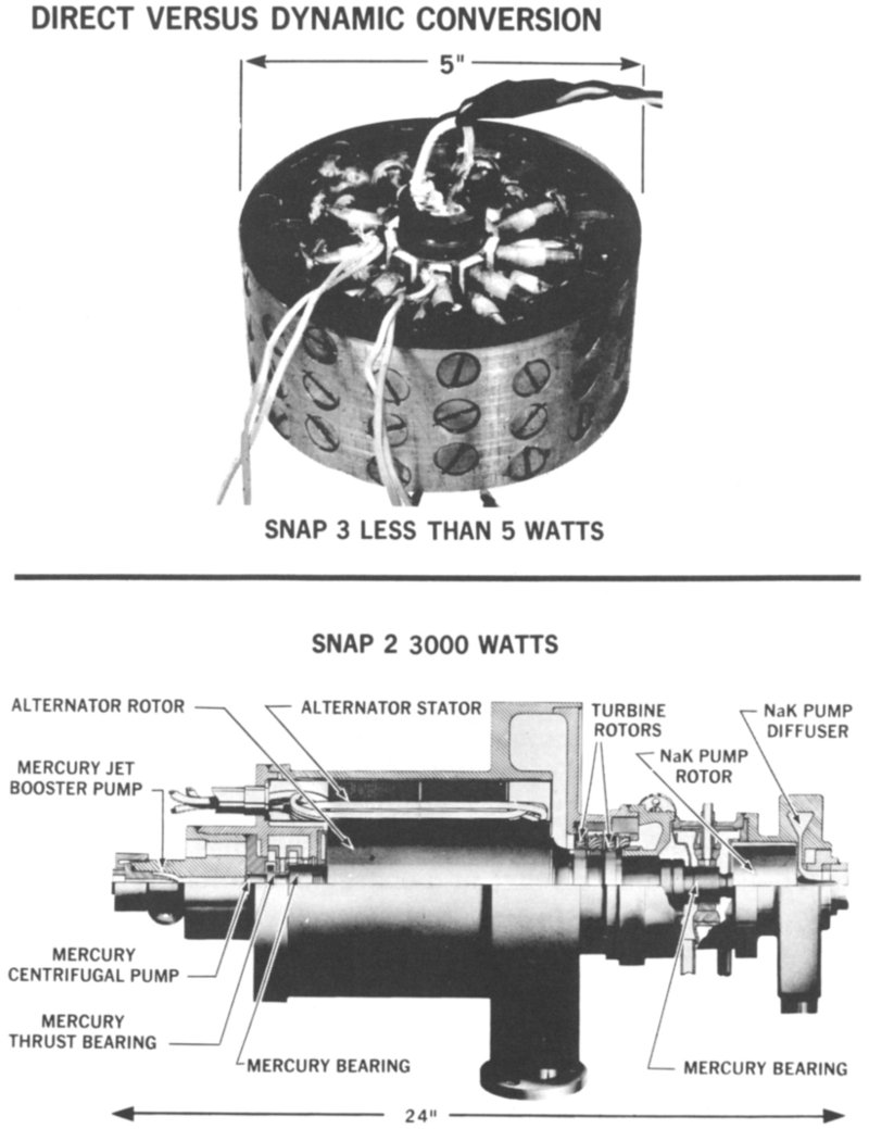
Figure 1 Direct conversion devices, such as the spokelike lead telluride thermoelectric elements inside the SNAP 3 radioisotope generator shown above (courtesy Martin Company), convert heat into electricity without moving parts. In contrast, the SNAP 2 dynamic converter shown below SNAP 3 (courtesy Thompson Ramo Wooldridge, Inc.) includes a high-speed turbine, an electric generator, and pumps to produce electricity from heat. (NaK is a liquid mixture of sodium and potassium.)
- DIRECT VERSUS DYNAMIC CONVERSION
- SNAP 3 LESS THAN 5 WATTS
- 5″
- SNAP 2 3000 WATTS
- 24″
- ALTERNATOR ROTOR
- ALTERNATOR STATOR
- TURBINE ROTORS
- NaK PUMP DIFFUSER
- NaK PUMP ROTOR
- MERCURY JET BOOSTER PUMP
- MERCURY CENTRIFUGAL PUMP
- MERCURY THRUST BEARING
- MERCURY BEARING
- MERCURY BEARING
Why is Direct Conversion Desirable?
There are places where energy conversion equipment must run for years without maintenance or breakdown. Also, there are situations where the ultimate in reliability is required, such as on scientific satellites and particularly on manned space flights. Direct conversion equipment seems to offer greater reliability than dynamic conversion equipment for these purposes.
We should recognize that our belief in the superiority of direct conversion is based more on intuition than proof. It is true that direct converters will never throw piston rods or run out of lubricant. Yet, some satellite power failures have been caused by the degradation of solar cells under the bombardment of solar protons. The other types of direct conversion devices described in the following pages may also break down in ways as yet unknown. Still, today’s knowledge gives us hope that direct conversion will be more reliable and trustworthy than dynamic conversion. Direct conversion equipment is beginning to be adopted for small power plants, producing less than 500 watts, designed to operate for long periods of time in outer space and under the ocean. Some day, large central-station power plants may use direct conversion to improve their efficiencies and reliabilities.
How is Energy Transformed?
What is energy and how do we change it? Energy is a fundamental concept of science involving the capacity for doing work. Kinetic or mechanical energy is the most obvious form of energy. It is defined as
E = ½ mv²
where
E = energy (expressed in joules)
m = mass of the moving object (in kilograms)
v = velocity (in meters per second)
Energy can also be stored in chemical and nuclear substances or in the water behind a dam. In these quiescent states it is called potential energy. If the potential energy in a substance is abundant and easily released, the energy-rich substance is called a fuel.
ENERGY CONVERSION MATRIX
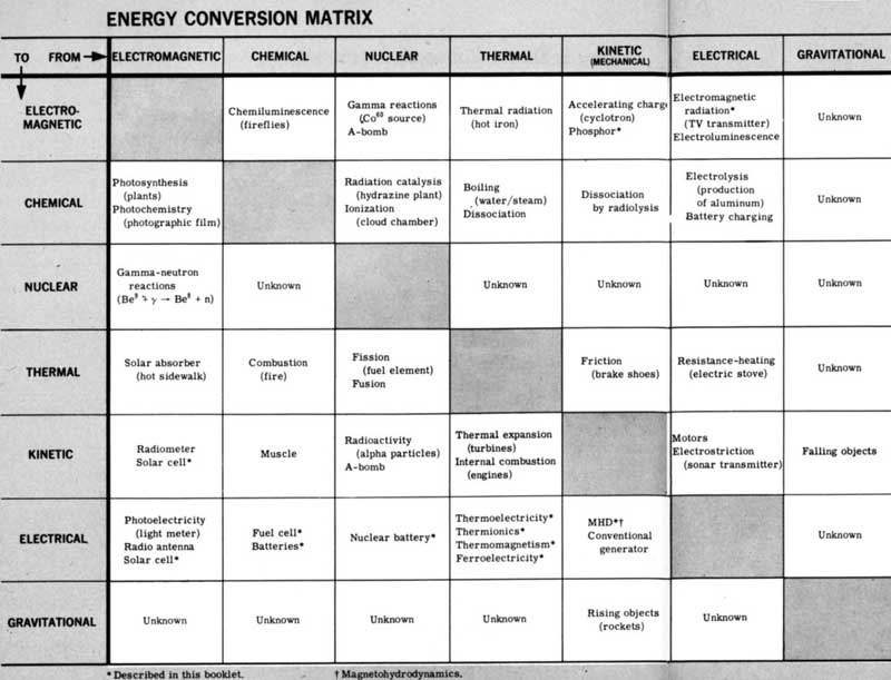
Figure 2 To find how one form of energy is converted into another, start at the proper column and move down until the column intersects with the desired row. The box at the intersection will give typical conversion processes and examples.
| FROM⇒ | ELECTROMAGNETIC | CHEMICAL | NUCLEAR | THERMAL | KINETIC (MECHANICAL) |
ELECTRICAL | GRAVITATIONAL |
|---|---|---|---|---|---|---|---|
| TO⇓ | |||||||
| ELECTROMAGNETIC | Chemiluminescence (fireflies) |
Gamma reactions (Co⁵⁸ source) A-bomb |
Thermal radiation (hot iron) |
Accelerating charge (cyclotron) Phosphor[2] |
Electromagnetic radiation[2] (TV transmitter) Electroluminescence |
Unknown | |
| CHEMICAL | Photosynthesis (plants) Photochemistry (photographic film) |
Radiation catalysis (hydrazine plant) Ionization (cloud chamber) |
Boiling (water/steam) Dissociation |
Dissociation by radiolysis | Electrolysis (production of aluminum) Battery charging |
Unknown | |
| NUCLEAR | Gamma-neutron reactions (Be⁹+γ → Be⁸+n) |
Unknown | Unknown | Unknown | Unknown | Unknown | |
| THERMAL | Solar absorber (hot sidewalk) |
Combustion (fire) |
Fission (fuel element) Fusion |
Friction (brake shoes) |
Resistance-heating (electric stove) |
Unknown | |
| KINETIC | Radiometer Solar cell[2] | Muscle | Radioactivity (alpha particles) A-bomb |
Thermal expansion (turbines) Internal combustion (engines) |
Motors Electrostriction (sonar transmitter) |
Falling objects | |
| ELECTRICAL | Photoelectricity (light meter) Radio antenna Solar cell[2] |
Fuel cell[2] Batteries[2] |
Nuclear battery[2] | Thermoelectricity[2] Thermionics[2] Thermomagnetism[2] Ferroelectricity[2] |
MHD[2][3] Conventional generator |
Unknown | |
| GRAVITATIONAL | Unknown | Unknown | Unknown | Unknown | Rising objects (rockets) |
Unknown |
The Energy Conversion Matrix
Forms of energy are interchangeable. When gasoline is burned in an automobile engine, potential energy is first turned into heat. A portion of this heat, say 25%, is then converted into mechanical motion. The remainder of the heat is wasted and must be removed from the engine.
A multitude of processes and devices have been found which make these transformations from one form of energy to another. Many of these are listed in the blocks in Figure 2. Asterisks refer to direct conversion processes, the subject matter of this booklet.
To demonstrate how this diagram is to be read, let us use it to trace the energy transformations involved in an automobile engine. We begin with sunlight because all coal and oil deposits (the fossil fuels) received their initial charge of energy in the form of sunlight.
The first conversion, therefore, is from electromagnetic energy to chemical energy via photosynthesis in living things. We trace the transformation by moving down the column marked Electromagnetic Energy until it intersects the horizontal row labeled Chemical Energy. There we see photosynthesis listed in the block. The next conversion is from chemical energy to thermal energy via combustion. 8 We trace this by moving down the Chemical Energy column to the Thermal Energy row; combustion is listed in the appropriate block. The third and final conversion takes place when thermal energy is transformed into mechanical energy via the internal combustion engine.
By the repeated use of the Energy Conversion Matrix in this way, we can chart any energy transformation.
Problem 1
Continue the automobile example by going through the matrix twice more showing how mechanical energy is converted into stored chemical energy in the car’s battery.
Problem 2
If 1 gram of gasoline (about a tablespoonful) yields 48,000 joules of thermal energy when burned with air, how fast can it make a 1000 kilogram car go? Assume the car starts from rest and its engine is 25% efficient.
Answers to problems are on page 34.
LAWS GOVERNING ENERGY CONVERSION
The Big Picture: Thermodynamics
To the best of our knowledge, energy and mass are always conserved together in any transformation. This summary of experience has been made into a keystone of science: the Law of Conservation of Energy and Mass. It states that the total amount of mass and energy cannot be altered. This law applies to everything we do, from driving a nail to launching a space probe. While the conscience of the scientist insists that he continually recheck the truth of this law, it remains a bulwark of science.
The Law of Conservation of Energy and Mass is also called the First Law of Thermodynamics. It is related to the Second Law of Thermodynamics, which also governs energy transformations. The Second Law says, in effect, that some energy will unavoidably be lost in all heat engines. The first two laws of thermodynamics have been paraphrased as (1) You can’t win; (2) You can’t even break even. Let us look at them further.
You Can’t Win
We used to think that energy and mass were conserved independently, and for many practical purposes we still consider them so conserved. But Einstein united the two with the famous equation
E = mc²
where
E = energy (in joules)
m = mass (in kilograms)
c = speed of light
(300,000,000 meters per second)
Notice the resemblance to the kinetic energy equation shown earlier. Energy cannot appear without the disappearance of mass. When energy is locked up in a fuel, it is stored as mass. In the gasoline combustion problem, 1 gram of gasoline was burned with air to give 48,000 joules of energy. Einstein’s equation says that in this case mass disappeared in the amount
m = E/c² = (4.8 × 10⁴)/(9 × 10¹⁶) = 5.3 × 10⁻¹³ kilogram
(half a billionth of a gram)
But, when an H-bomb is exploded, grams and even kilograms of mass are converted to energy.
In direct conversion processes we do not need to worry about these mass changes, but at each point we must make sure that all energy is accounted for. For example, in outer space all energy released from fuels (even food) must ultimately be radiated away to empty Space. Otherwise the vehicle temperature will keep rising until the Spaceship melts.
You Can’t Even Break Even
Any engineer is annoyed by having to throw energy away. Why is energy ever wasted? The Second Law of Thermodynamics guides us here. Experience has shown that heat cannot be transformed into another form of energy with 100% efficiency. We can’t explain Nature’s idiosyncracies, but we have to live with them. So, we accept the fact that every engine that starts out with heat must ultimately waste some of that energy (Figure 3).
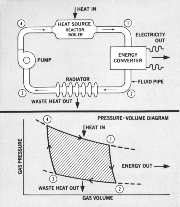
Figure 3 A typical heat engine showing heat input, useful power output, and the unavoidable waste heat that must be rejected to the environment. A pressure-volume diagram is shown underneath for a closed gas-turbine cycle. Circled numbers correspond. The energy produced is represented by the shaded area. Similar diagrams can be made for all heat engines as an aid in studying their performance.
- A TYPICAL HEAT ENGINE
- HEAT IN
- HEAT SOURCE
- REACTOR, BOILER
- ELECTRICITY OUT
- ENERGY CONVERTER
- PUMP
- FLUID PIPE
- RADIATOR
- WASTE HEAT OUT
- PRESSURE-VOLUME DIAGRAM
- HEAT IN
- ENERGY OUT
- GAS PRESSURE
- WASTE HEAT OUT
- GAS VOLUME
Direct conversion devices are no exception. Consequently, every thermoelectric element or thermionic converter will have to provide for the disposition of waste heat. The designer will try, however, to make the engine efficiency high so that the waste heat will be small. Figure 4 shows the extensive waste heat radiator on a SNAP 50 power plant planned for deep space missions.
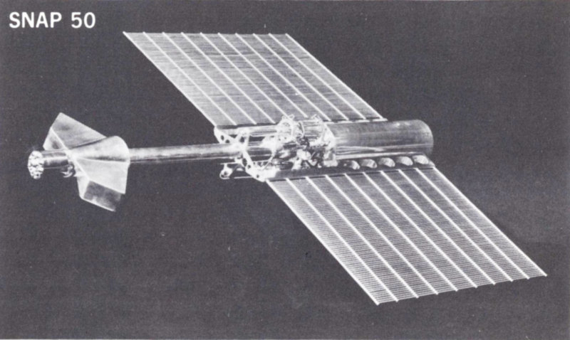
Figure 4 Model of SNAP 50 power plant planned for deep space missions showing extensive waste heat radiator. The system will provide 300 to 1000 kilowatts of electrical power.
Carnot Efficiency
In 1824 Sadi Carnot, a young French engineer, conceived of an idealized heat engine. This ideal engine had an efficiency given by
e = 1 - Tc/Th = (Th - Tc)/Th
where
e = the so-called Carnot efficiency (no units)
Tc = the temperature of the waste heat reservoir (in degrees Kelvin, °K[4])
Th = the temperature of the heat source (in °K)
Unhappily, Tc cannot be made zero (and e therefore made equal to 1, which is 100% efficiency). Physicists have shown absolute zero to be unattainable, although they have approached to within a hundredth of a degree in the laboratory.
Waste heat, since it must be rejected to the surrounding atmosphere, outer space, or water (rivers, the ocean, etc.), must be rejected at Tc greater than 300°K. The reason for this is that these physical reservoirs have average temperatures around 300°K (about 80°F) themselves. The fact that Tc must be 300°K or more is a basic limitation on the Carnot efficiency. The loss in efficiency with increased Tc explains why a jet plane has a harder job taking off on a hot day.
One way to improve the Carnot efficiency, which is the maximum efficiency for any heat engine, is to raise Th as high as possible without melting the engine. For a coal-fired electrical power plant, Th = 600°K and Tc = 300°K, so that
e = 1 - 300/600 = 0.5 = 50%
The actual efficiency is somewhat less than this ideal value because some power is diverted to pumps and other 12 equipment and to unavoidable heat losses. Later on, we shall see that magnetohydrodynamic (MHD) generators hold prospects for increasing Th by hundreds of degrees.
Everything that has been said about the Second Law of Thermodynamics (You can’t even break even) applies to heat engines, where we begin with thermal energy. Suppose instead that we start with kinetic or chemical energy and convert it into electricity without turning it into heat first. We can then escape the Carnot efficiency strait jacket. Chemical batteries perform this trick. So do fuel cells, solar cells, and many other direct conversion devices we shall discuss. Thus, we circumvent the Carnot efficiency limitation by using processes to which it does not apply.
Problem 3
Some space power plants contemplate using the space cabin heat (Th = 300°K) to drive a heat engine which rejects its waste heat to the liquid-hydrogen rocket fuel stored at Tc = 20°K. What would be the Carnot efficiency of this engine?
THERMOELECTRICITY
After 140 Years: Seebeck Makes Good
The oldest direct conversion heat engine is the thermocouple. Take two different materials (typically, two dissimilar metal wires), join them, and heat the junction. A voltage, or electromotive force, can be measured across the unheated terminals. T. J. Seebeck first noticed this effect in 1821 in his laboratory in Berlin, but, because of a mistaken interpretation of what was involved, he did not seek any practical application for it. Only recently has any real progress been made in using his discovery for power production. To use the analogy of A. F. Joffe, the Russian pioneer in this field, thermoelectricity lay undisturbed for over a hundred years like Sleeping Beauty. The Prince that awoke her was the semiconductor.
As long as inefficient metal wires were used, textbook writers were correct in asserting that thermoelectricity could never be used for power production. The secret of 13 practical thermoelectricity is therefore the creation of better thermoelectric materials. (Creation is the right word since the best materials for the purpose do not exist in nature.) To perform this alchemy, we first have to understand the Seebeck effect.
Electrons and Holes
Let’s examine the latticework of atoms that make up any solid material. In electrical insulators all the atoms’ outer electrons[5] are held tightly by valence bonds to the neighboring atoms. In contrast, any metal has many relatively loose electrons which can wander freely through its latticework. This is what makes metals good conductors.
THERMOELECTRICITY
Figure 5 Thermoelectric couple made from p- and n-type semiconductors. The impurity atoms (I) are different in each leg and contribute an excess or deficiency of valence electrons. Heat drives both holes and electrons toward the cold junction.
- Tc WASTE HEAT OUT
- ELECTRONS
- LOAD
- COLD JUNCTION
- HOLES
- ELECTRONS
- p SEMICONDUCTOR
- n SEMICONDUCTOR
- HOT JUNCTION
- Th HEAT IN
- Simplified Sketch of Atomic Lattice
- HOLE
- ELECTRON
- VALENCE BONDS
- SEMICONDUCTOR LATTICES
- I = Impurity atom
Figure 5 suggests the latticework of a semiconductor. It is called a semiconductor because its conductivity falls far short of that of the metals. The few electrons available for carrying electricity are supplied by the deliberately introduced 14 impurity atoms, which have more than enough electrons to satisfy the valence-bond requirements of the neighboring atoms. Without the impurities, we would have an insulator. With them, we have an n-type semiconductor. The n is for the extra negative electrons.
A p- or positive-type semiconductor is also included in Figure 5. Here the impurity atom does not have enough valence electrons to satisfy the valence-bond needs of the surrounding lattice atoms. The lattice has been short-changed and is, in effect, full of positive holes. Strangely enough, these holes can wander through the material just like positive charges.
The electron-hole model does not have the precision the physicist likes, but it helps us to visualize semiconductor behavior.
The Seebeck effect is demonstrated when pieces of p- and n-type material are joined as shown in Figure 5. Heat at the hot junction drives the loose electrons and holes toward the cold junction. Think of the holes and electrons as gases being driven through the latticework by the temperature difference. A positive and a negative terminal are thus produced, giving us a source of power. The larger the temperature difference, the bigger the voltage difference. Note that just one thermocouple leg can produce a voltage across its length, but couples made from p and n legs are superior.
Practical Thermoelectric Power Generators
The first nuclear-heated thermoelectric generator was built in 1954 by the Atomic Energy Commission’s Mound Laboratory in Miamisburg, Ohio. It used metal-wire thermocouples. In contrast, the SNAP 3 series thermocouples shown in Figure 1 are thick lead telluride (PbTe) semiconductor cylinders about two inches long. In contrast to the thermocouple wires’ efficiency of less than 1%, SNAP 3 series generators have overall efficiencies exceeding 5%. This value is still low compared to the 35-40% obtained in a modern steam power plant, but SNAP 3 generators can operate unattended in remote localities where steam plants would be totally unacceptable.
Look again at the thermoelements in Figure 1 and the schematic, Figure 5. Underlying the apparent simplicity of 15 the thermoelectric generator are extensive development efforts. The Figure 1 thermoelectric couple, for example, shows the fruits of thousands of experimental brazing tests. It turns out to be uncommonly difficult to fasten thermoelectric elements to the so-called hot shoe (metal plate) at the bottom. The joint has to be strong, must withstand high temperatures, and must have low electrical resistance. We see also that the elements are encased in mica sleeves to prevent chemical disturbance of the delicate balance of impurities in the semiconductor by the surrounding gases. A further complication is the extreme fragility of the elements, and this has yet to be overcome.
Nuclear thermoelectric generators that provide small amounts of electrical power have already been launched into space aboard Department of Defense satellites (Figure 12), installed on land stations in both polar regions, and placed under the ocean.[6] Propane-fueled thermoelectric generators, such as shown in Figure 6, are now on the market for use in camping equipment, in ocean buoys, and in remote spots where only a few watts of electricity are needed. The Russians have long manufactured a kerosene lamp with thermoelements placed in its stack for generating power in wilderness areas.
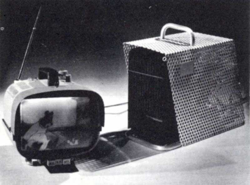
Figure 6 GENERAL PURPOSE GENERATOR
Commercially available thermoelectric generators using propane fuel can provide more than enough electrical power to operate a portable TV set. Courtesy Minnesota Mining & Manufacturing Company.
For the present the role of thermoelectric power appears to be one of special uses such as those just mentioned. When higher efficiencies are attained, thermoelectric power may, one day, supplant dynamic conversion equipment in certain low-power applications regardless of location.
THERMIONIC CONVERSION
“Boiling” Electrons Out of Metals
Like the thermoelectric element, the thermionic converter is a heat engine. In its simplest form it consists of two closely spaced metallic plates and resembles the diode radio tube. Whereas thermoelectric elements depend on heat to drive electrons and holes through semiconductors to an external electricity-using device or load, the salient feature of the thermionic diode is thermionic emission,[7] or, simply, the boiling-off of electrons from a hot metal surface. The thermionic converter shown in Figure 7 powers a small motor when heated by a torch.
Metals, as we have already seen, have an abundance of loosely bound conduction electrons roaming the atomic latticework. These electrons are easily moved by electric fields while within the metal; but it takes considerably more energy to boil them out of the metal into free space. Work has to be done against the electric fields set up by the surface layer of atoms, which have unattached valence bonds on the side facing empty space.
The energy required to completely detach an electron from the surface is called the metal’s work function. In the case of tungsten, for example, the work function is about 4.5 electron volts[8] of energy.
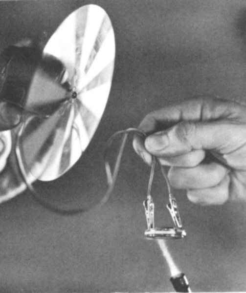
Figure 7 Vacuum type thermionic converter in operation. Courtesy General Electric Company.
As we raise the temperature of a metal, the conduction electrons in the metal also get hotter and move with greater velocity. We may think of some of the electrons in a metal as forming a kind of electron gas. Some electrons will gain such high speeds that they can escape the metal surface. 17 This happens when their kinetic energy exceeds the metal’s work function.
Now that we have found a way to force electrons out of the metal, we would like to make them do useful electrical work. To do this we have to push the electrons across the gap between the plates as well as create a voltage difference to go with the hoped-for current flow.
Reducing the Space Charge
The emitted or boiled-off electrons between the converter plates (Figure 8) form a cloud of negative charges that will repel subsequently emitted electrons back to the emitter plate unless counteraction is taken. To circumvent these space charge effects, we fill the space between the plates with a gas containing positively charged particles. These mix with the electrons and neutralize their charge. The mixture of positively and negatively charged particles is called a plasma.
The presence of the plasma makes the gas a good conductor. The emitted electrons can now move easily across it to the collector where, to continue the gas analogy, they condense on the cooler surface.
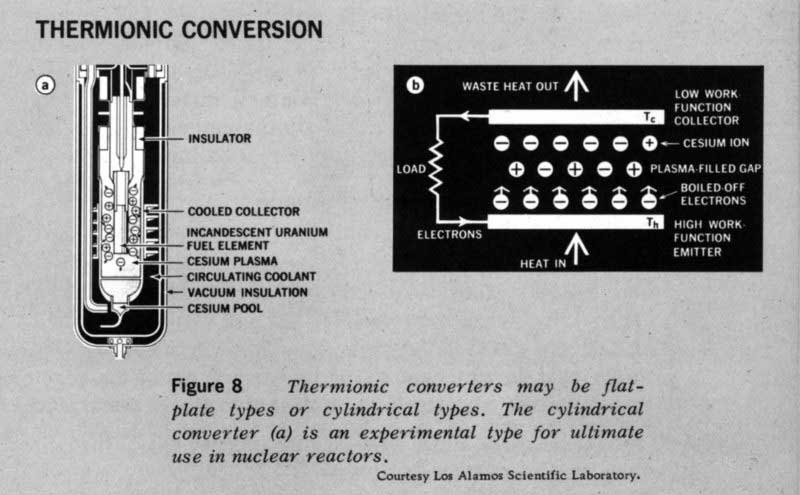
Figure 8 THERMIONIC CONVERSION
Thermionic converters may be flat-plate types or cylindrical types. The cylindrical converter (a) is an experimental type for ultimate use in nuclear reactors. Courtesy Los Alamos Scientific Laboratory.
- a
- INSULATOR
- COOLED COLLECTOR
- INCANDESCENT URANIUM
- FUEL ELEMENT
- CESIUM PLASMA
- CIRCULATING COOLANT
- VACUUM INSULATOR
- CESIUM POOL
- b
- WASTE HEAT OUT
- LOAD
- ELECTRONS
- LOW WORK FUNCTION COLLECTOR
- Tc
- CESIUM ION
- PLASMA FILLED GAP
- BOILED OFF ELECTRONS
- HIGH WORK FUNCTION EMITTER
- Tc
- HEAT IN
Result: A Plasma Thermocouple
Unless a voltage difference exists across the plates, no external work can be done. In the thermocouple the voltage difference was caused by the different electrical properties of the p and n semiconductors. Both the emitter and collector in the thermionic converter are good metallic conductors rather than semiconductors, so a different tack must be taken.
The key is the use of an emitter and a collector with different work functions. If it takes 4.5 electron volts to force an electron from a tungsten surface and if it regains only 3.5 electron volts when it condenses on a collector with a lower work function, then a voltage drop of 1 volt exists between the emitter and collector.
To summarize, then, the thermionic emission of electrons creates the potentiality of current flow. The difference in work functions makes the thermionic converter a power producer.
There is an interesting comparison that helps describe this phenomenon. Consider the emitter to be the ocean surface and the collector a mountain lake. The atmospheric heat engine vaporizes ocean water and carries it to the cooler mountain elevations, where it condenses as rain which collects in lakes. The lake water as it runs back toward sea level then can be made to drive a hydroelectric plant with the gravitational energy it has gained in the transit. The thermionic converter is similar in behavior: hot emitter (corresponding to the sun-heated ocean); cooler collector (lake); electron gas (water); different electrical voltages (gravity). Without gravity the river would not flow, and the production of electricity would be impossible.
Thermionic Power in Outer Space
Thermionic converters for use in outer space may be heated by the sun, by decaying radioisotopes, or by a fission reactor. Thermionic converters can also be made into concentric cylindrical shells (Figure 8a) and wrapped around the uranium fuel elements in nuclear reactors. The waste heat in this case would be carried out of the reactor to a separate radiator[9] by a stream of liquid metal. Since 19 thermionic converters can operate at much higher temperatures than thermoelectric couples or dynamic power plants, the radiator temperature, Tc, will also be higher. Consequently, space power plants using thermionic converters will have small radiators. Once thermionic converters are developed which have high reliability and long life, they will provide the basis for a new series of lighter, more efficient space power plants.
MAGNETOHYDRODYNAMIC CONVERSION
Big Word, Simple Concept
Magnetohydrodynamic (MHD) conversion is very unlike thermoelectric or thermionic conversion. The MHD generators use high-velocity electrically conducting gases to produce power and are generically closer to dynamic conversion concepts. The only concept they carry forward from the preceding conversion ideas is that of the plasma, the electrically conducting gas. Yet they are commonly classified as direct because they replace the rotating turbogenerator of the dynamic systems with a stationary pipe or duct.
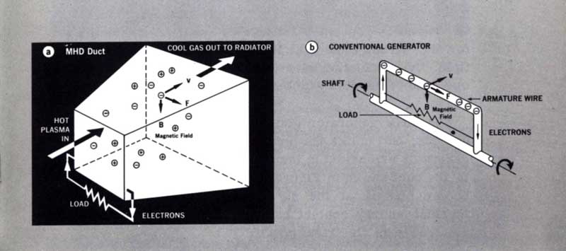
Figure 9 In the MHD duct (a), the electrons in the hot plasma move to the right under influence of force F in the magnetic field B. The electrons collected by the right-hand side of the duct are carried to the load. In a wire in the armature of a conventional generator (b) the electrons are forced to the right by the magnetic field.
- a
- MHD Duct
- HOT PLASMA IN
- COOL GAS OUT TO RADIATOR
- Magnetic Field
- LOAD
- ELECTRONS
- b
- CONVENTIONAL GENERATOR
- SHAFT
- LOAD
- Magnetic Field
- ARMATURE WIRE
- ELECTRONS
In the conventional dynamic generator, an electromotive force is created in a wire that cuts through magnetic lines of force, as shown in Figure 9b. It may be helpful to visualize the conduction electrons as leaving one end of the wire and moving to the other under the influence of the magnetic field.
The force on the electrons in the wire is given by
F = qvB
where
F = the force (in newtons[10])
q = the charge on the electron (1.6 × 10⁻¹⁹ coulomb)
v = the wire’s velocity (in meters per second)
B = the magnetic field strength (in webers per square meter[10])
The surge of electrons along the length of the wire sets up a voltage difference across the ends of the wire. A generator uses this difference to convert the kinetic energy of the moving wire or armature into electrical energy. The wire is kept spinning by the shaft which is connected to a turbine driven by steam or water.
Let us try to eliminate the moving part, the generator armature. What we need is a moving conductor that has no shaft, no bearings, no wearing parts. The substance that meets these requirements is the plasma. Examine Figure 9a. The MHD generator substitutes a moving, conducting gas for the wires. Under the influence of an external magnetic field, the conduction electrons move through the plasma to one side of the duct which carries electrical power away to the load.
The MHD generator gets its energy from an expanding, hot gas; but, unlike the turbogenerator, the heat engine and generator are united in the static duct. The gradual widening of the duct shown in Figure 9a reflects the lower pressure, cooler plasma at the duct’s end. Some of the plasma’s thermal energy content has been tapped off by the duct’s electrodes as electrical power.
The Fourth State of Matter
Plasma can be created by temperatures over 2000°K. At this temperature many high-velocity gas atoms collide with enough energy to knock electrons off each other and thus become ionized. The material thus created, shown as a glowing gas in Figure 10, does not behave consistently as any of the three familiar states of matter: solid, liquid, or gas. Plasma has been called a fourth state of matter. Since we have difficulty in containing such high temperatures on earth, we adopt the strategy of seeding. In this technique gases that are ordinarily difficult to ionize, like helium, are made conducting by adding a fraction of a percent of an alkali metal such as potassium. Alkali metal atoms have loosely bound outer electrons and quickly become ionized at temperatures well below 2000°K.
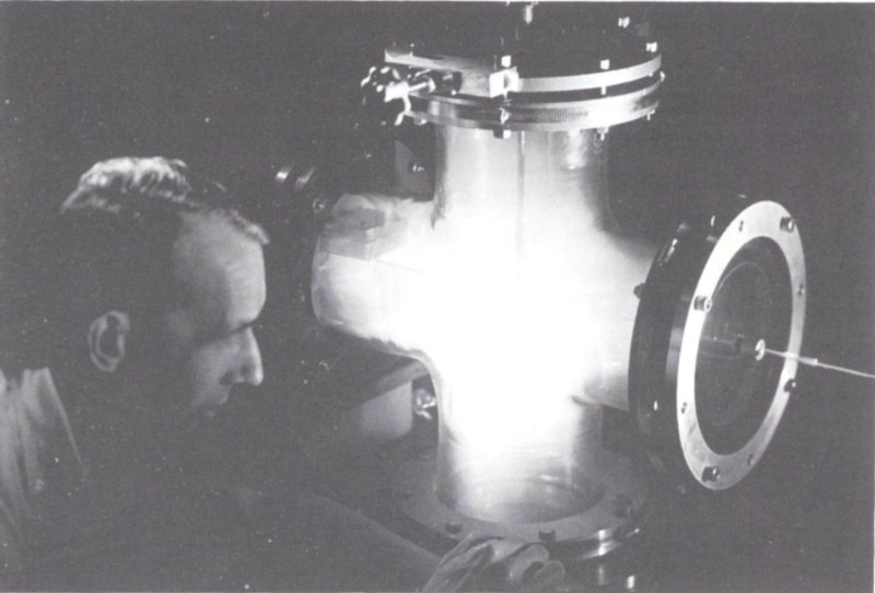
Figure 10 Glowing plasma in experimental device at General Atomic’s John Jay Hopkins Laboratory, San Diego. T-shaped plasma gun provides data for research in thermonuclear fusion. Courtesy Texas Atomic Energy Research Foundation.
A helium-potassium mixture is a good enough conductor for use in an MHD generator. In this plasma the electrons move rapidly under the influence of the applied fields, though not as well as in metals. The positive ions move in the opposite direction from the electrons, but the electrons are much lighter and move thousands of times faster thus carrying the bulk of the electrical current.
MHD Power Prospects
The MHD duct is not a complete power plant in itself because, after leaving the duct, the stream of gas must be compressed, heated, and returned to the duct. Very high temperature materials and components must be developed for this kind of service. Moreover, while the duct is simple in concept, it must operate at very high temperatures in the presence of the corrosive alkali metals. This presents us with difficult materials problems. When the problems are solved, probably within the next decade, MHD power plants should be able to provide reliable power with high efficiency. They may then serve in large space power plants, and, most important, they may provide cheaper electricity for general use through their higher temperatures and greater efficiencies.
CHEMICAL BATTERIES
Electricity from the Chemical Bond
If you vigorously knead a lemon to free the juices and then stick a strip of zinc in one end and a copper strip in the other, you can measure a voltage across the strips. Electrons will flow through the load without the inconvenience of having to supply heat. You have made yourself a chemical battery.
The chemical battery was the first direct conversion device. Two hundred years ago it was the scientists’ only continuous source of electricity.
Since the chemical battery does not need heat for its operation, it is logical to ask what makes the current flow. Where does the energy come from?
The battery has no semiconductors, but, like the thermoelectric couple and the thermionic diode, it uses dissimilar materials for its electrodes. A conducting fluid or solid is also present to provide for the passage of current between the electrodes. In the example of the lemon, the copper and zinc are the dissimilar electrodes, and the lemon juice is the conducting fluid or electrolyte that supplies positive and negative ions. The battery derives its energy from its complement of chemical fuel. The voltage difference arises 23 because of the different strengths of the chemical bonds. The chemical bond is basically an electrostatic one; some atoms have stronger electrical affinities than others.
Chemical Reactions Used in Batteries and Fuel Cells
Consider the following chemical reactions of common batteries together with some fuel cell reactions which will be discussed further in the next section.
- Battery Reactions
- Pb + PbO₂ + 2H₂SO₄ ⇔ 2PbSO₄ + 2H₂O
- Fe + NiO₂ ⇔ FeO + NiO
- Zn + AgO + H₂O ⇔ Ag + Zn(OH)₂
- Pb + Ag₂O ⇔ PbO + 2Ag
- Fuel Cell Reactions
- 2LiH ⇔ 2Li + H₂
- 2CuBr₂ ⇔ 2CuBr + Br₂
- 2H₂ + O₂ ⇔ 2H₂O (Bacon cell)
- PbI₂ ⇔ Pb + I₂
In principle all these reactions are the same as those going on inside the lemon, although each type of cell produces a slightly different voltage because of the varying chemical affinities of the atoms and molecules involved. There are literally hundreds of materials which can be used for electrolytes and electrodes.
No heat needs to be added as the electrostatic chemical bonds are broken and remade in a battery to generate electrical power. The chemical reaction energy is transferred to the electrical load with almost 100% efficiency. The Carnot cycle is no limitation here; only “cold” electrostatic forces are in action. The reactions cannot go on forever, however, because the battery supplies the energy converter with a very limited supply of fuel. Eventually the fuel is consumed and the voltage drops to zero. This deficiency is remedied by the fuel cell in which fuel is supplied continuously.
An Old Standby in Outer Space
Almost every satellite and space vehicle has a chemical battery aboard. It is not there so much for continuous power production but as a rechargeable electrical accumulator or reservoir to provide electricity during peak loads. The battery is also needed to store energy for use during the periods when solar cells are in the earth’s shadow and therefore inoperative. In this capacity the dependable old battery serves the most modern science very well indeed.
THE FUEL CELL: A CONTINUOUSLY FUELED BATTERY
Potential Fuels
The battery has a very close relative, the fuel cell. Unlike the battery the fuel cell has a continuous supply of fuel.
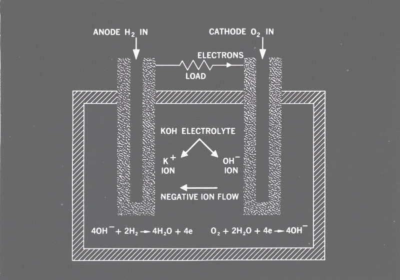
Figure 11 This diagram shows how a hydrogen-oxygen fuel cell works. The chemical battery works in the same way, except that the chemicals are different and are not continuously supplied from outside the cell. The water produced by the H-O cell shown can be used for drinking on spaceships.
- ANODE H₂ IN
- CATHODE O₂ IN
- ELECTRONS
- LOAD
- KOH ELECTROLYTE
- K⁺ ION
- OH⁻ ION
- NEGATIVE ION FLOW
- 40H⁻ + 2H₂ ⇒ 4H₂O + 4e
- O₂ + 2H₂O + 4e ⇒ 40H⁻
The hydrogen-oxygen cell of Figure 11 is typical of all fuel cells. It essentially burns hydrogen and oxygen to form water. If the hydrogen and oxygen can be supplied continuously and the excess water drained off, we can greatly extend the life of the battery. The fuel cell accomplishes this. Fueled electrical cell would be more descriptive since the physical principles are identical with those of the battery.
Perhaps the most challenging task contemplated for the fuel cell is to bring about the consumption of raw or slightly processed coal, gas, and oil fuels with atmospheric oxygen. If fuel cells can be made to use these abundant fuels, then the high natural conversion efficiency of the fuel cells will make them economically superior to the lower efficiency steam-electric plants now in commercial service.
So far we have dwelt on the fuel cell as a cold energy conversion device that is not limited by the Carnot efficiency. A variation on this theme is possible. Take a hydrogen iodide (HI) cell, and heat the HI to 2000°K. Some of the HI molecules will collide at high velocities and dissociate into hydrogen and iodine: 2HI = H₂ + I₂; the higher the temperature, the more the dissociation. By separating the hydrogen and iodine gases and returning them for recycling to the fuel cell where they are recombined, we have eliminated the fuel supply problem and created a regenerative fuel cell. We have, however, also reintroduced the heat engine and the Carnot cycle efficiency. The thermally regenerative fuel cell is a true heat engine using a dissociating gas as the working fluid.
Scheme for Project Apollo
Most of the impetus for developing the fuel cell as a practical device comes from the space program. The cell has admirable properties for space missions that are less than a few months in duration. It is a clean, quiet, vibrationless source of energy. Like the battery it has a high electrical overload capacity for supplying power peaks and is easily controlled. It can even provide potable water for a crew if the Bacon H - O cell is used. For short missions where large fuel supplies are not needed, it is also among the lightest power plants available.
These compelling advantages have led the National Aeronautics and Space Administration to choose the fuel cell for some of the first manned space ventures. Project Apollo, the manned lunar landing mission, is the most notable example. Here the fuel cell will be not only an energy source, but also part of the ecological cycle which keeps the crew alive.
Problem 4
A manned space vehicle requires an average of 2 electrical kilowatts. A nuclear reactor thermoelectric plant having a mass of 1000 kilograms, including shielding, can supply this power for 10,000 hours. The basic fuel cell has a mass of 50 kilograms and consumes ½ kilogram of chemicals per hour. The chemical containers weigh 25 kilograms. What is the longest mission where the total weight of the fuel cell will be less than the weight of the nuclear power plant?
SOLAR CELLS
Photons as Energy Carriers
All our fossil fuels, such as coal and oil, owe their existence to the solar energy stream that has engulfed the earth for billions of years. The power in this stream amounts to about 1400 watts per square meter at the earth, nearly enough to supply an average home if all the energy were converted to electricity. The problem is to get the sun’s rays to yield up their energy with high efficiency.
The sun’s visible surface has a temperature around 6000°K. Any object heated to this temperature will radiate visible light mostly in the yellow-green portion of the spectrum (5500 A[11]). Our energy conversion device should be tuned to this wavelength.
The energy packets arriving from the sun are called photons. They travel, of course, at the speed of light, and each carries an amount of energy given by
E = hf = hc/λ
where
E = energy (in joules)
h = Planck’s constant (6.62 × 10⁻³⁴ joule-second)
f = the light’s frequency (in cycles per second = c/λ)
c = the velocity of light (300,000,000 meters per second)
λ = the wavelength (in meters)
Using the fact that an angstrom unit is 10⁻¹⁰ meter, the energy of a 5500 A photon could be calculated as
E = hf = hc/λ = (6.62 × 10⁻³⁴ × 3.00 × 10⁸)/(5.50 × 10⁻⁷)
= 3.61 × 10⁻¹⁹ joule = 2.2 electron volts
Comparing this result, 2.2 electron volts, with the energies required to cause atomic ionization or molecular dissociation 27 (an electron volt or so), we see that it is in the right range to actuate direct conversion devices based on such phenomena.
Harnessing the Sun’s Energy
Historically, the sun’s energy has most often been used by concentrating it with a lens or mirror and then converting it to heat. We could do this and run a heat engine, but a more direct avenue is open.
About a decade ago it was found that the junction between p and n semiconductors would generate electricity if illuminated. This discovery led to the development of the solar cell, a thin, lopsided sandwich of silicon semiconductors. As shown in Figure 12, the top semiconductor layer exposed to the sun is extremely thin, only 2.5 microns. Solar photons can readily penetrate this layer and reach the junction separating it from the thick main body of the solar cell.
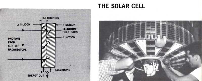
Figure 12 THE SOLAR CELL
The photograph shows the solar cell in use on a satellite. The spherical, radioisotope, thermoelectric generator at the bottom of the satellite is used to supplement the solar cells. In the solar cell, hole-electron pairs are created by solar photons in the vicinity of a p-n junction. Courtesy U. S. Air Force and National Aeronautics and Space Administration.
- p SILICON
- n SILICON
- ELECTRON-MOLE PAIRS
- JUNCTION
- PHOTONS FROM SUN OR RADIOISOTOPE
- ELECTRONS
- ENERGY OUT
Whenever p- and n-type semiconductors are sandwiched together a voltage difference is created across the junction. The separated holes and electrons in the two semiconductor regions establish this electric field across the junction. Unfortunately, there are usually no current carriers in the immediate vicinity of the junction so that no power is produced.
The absorption of solar photons in the vicinity of the junction will create current carriers, as the photons’ energy is transformed into the potential energy of the hole-electron pairs. These pairs would quickly recombine and give up their newly acquired potential energy if the electric field existing across the junction did not whisk them away to an external load.
The solar cell produces electricity when hole-electron pairs are formed. Any other phenomenon that creates such pairs will also generate electricity. The source of energy is irrelevant so long as the current carriers are formed near the junction. Thus, particles emitted by radioactive atoms can also produce electricity from solar cells, although too much bombardment by such particles can damage the cell’s atomic structure and reduce its output.
The solar cell is not a heat engine. Yet it loses enough energy so that the sun’s energy is converted at less than 15% efficiency. Losses commonly occur because of the recombination of the hole-electron pairs before they can produce current, the absorption of photons too far from the junction, and the reflection of incident photons from the top surface of the cell. Despite these losses solar cells are now the mainstay of nonpropulsive space power.
NUCLEAR BATTERIES
Energy from Nuclear Particles
As we have seen, solar cells are able to convert the kinetic energy of charged nuclear particles directly into electricity, but a simpler and more straightforward way of doing this exists. This involves direct use of the flow of charged particles as current.
The nuclear battery shown in Figure 13 performs this trick. A central rod is coated with an electron-emitting radioisotope (a beta-emitter; say, strontium-90). The high-velocity electrons emitted by the radioisotope cross the gap between the cylinders and are collected by a simple metallic sleeve and sent to the load. Simple, but why don’t space 29 charge effects prevent the electrons from crossing the gap as they do in the thermionic converter? The answer lies in the fact that the nuclear electrons have a million times more kinetic energy than those boiled off the thermionic converter’s emitter surface. Consequently, they are too powerful to be stopped by any space charge in the narrow gap.
Nuclear batteries are simple and rugged. They generate only microamperes of current at 10,000 to 100,000 volts.

Figure 13 A NUCLEAR BATTERY
The nuclear battery depends upon the emission of charged particles from a surface coated with a radioisotope. The particles are collected on another surface.
- ENERGY OUT
- INSULATOR
- LAYER OF BETA-EMITTING RADIOISOTOPE
- VACUUM
Double Conversion
In the earlier description of the energy conversion matrix, we saw that we could go through the energy transformation process repeatedly until we obtained the kind of energy we wanted. This is exemplified in a type of nuclear battery which uses the so-called double conversion approach. First, the high-velocity nuclear particles are absorbed in a phosphor which emits visible light. The photons thus produced are then absorbed in a group of strategically placed solar cells, which deliver electrical power to the load. Although efficiency is lost at each energy transformation, the double conversion technique still ends up with an overall efficiency of from 1 to 5%, an acceptable value for power supplies in the watt and milliwatt ranges.
ADVANCED CONCEPTS
Ferroelectric and thermomagnetic conversion are subtle concepts which depend upon the gross alteration of a material’s physical properties by the application of heat. Devices employing such concepts are true heat engines. Instead of the gaseous and electronic working fluids used in the other direct conversion concepts, the ferroelectric and thermomagnetic concepts employ patterns of atoms and molecules that are actually rearranged periodically by heat.
Ferroelectric Conversion
Ferroelectric conversion makes use of the peculiar properties of dielectric[12] materials. Barium titanate, for example, has good dielectric properties at low temperatures, but, when its temperature is raised to more than 120°C, the properties get worse rapidly. We cannot discuss dielectric behavior thoroughly in this booklet; suffice it to say that in this process heat is absorbed in a realignment of molecules within the barium titanate latticework.
If we now place a slab of barium titanate between the two plates of an electrical condenser and charge the condenser, as shown in Figure 14, we have a unique way of converting heat into electricity directly. When the barium titanate is heated above its Curie point[13] of 120°C, the condenser’s capacitance is radically reduced as the dielectric constant falls. The condenser is forced to discharge and move electrons through an external circuit consisting of the load and the original source of charge. Useful electrical energy is delivered during this step. Figure 14 shows the process schematically and mathematically. When the dielectric is cooled, waste heat is given up by the barium titanate, and the cycle is complete.
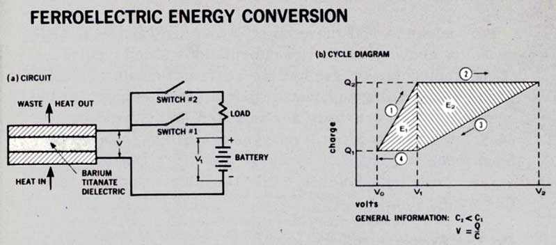
Figure 14 FERROELECTRIC ENERGY CONVERSION
The ferroelectric converter is really an electrical capacitor whose capacitance is changed by temperature. When heat is added, capacitance drops, voltage rises, and the capacitor is made to discharge through the load. CYCLE: ① Switch #1 closed, #2 open. Condenser charges from battery to charge Q₂ at voltage V₁ with capacity C₁. ② All switches open. Heat added, capacity changes from C₁ to C₂, charge remains constant, so voltage changes from V₁ to V₂. ③ Switch #2 closed, #1 open. Condenser discharges through load and battery to charge Q₁ at voltage V₁ with capacity C₂. ④ All switches open. Heat rejected, capacity changes from C₂ to C₁, charge remains constant, so voltage changes from V₁ to V₀. CYCLE THEN REPEATS. Energy supplied from battery each cycle is E₁. Energy delivered to load and battery each cycle is E₂. Net energy converted is then E₂ - E₁, the difference in the shaded areas.
- (a) CIRCUIT
- HEAT IN
- BARIUM TITANATE DIELECTRIC
- WASTE HEAT OUT
- SWITCH #2
- LOAD
- SWITCH #1
- BATTERY
- (b) CYCLE DIAGRAM
- charge
- volts
- Q₂, Q₁, E₁, E₂, V₀ V₁ V₂
- GENERAL INFORMATION:
- C₂ < C₁
- V = Q/C
Thermomagnetic Conversion
The analog[14] of ferroelectricity is ferromagnetism. A converter employing similar principles to those in ferroelectricity can be made using an electrical inductance with a ferromagnetic core. When the temperature of the ferromagnetic material is raised above its Curie point, its magnetic permeability drops quickly, causing the magnetic field to collapse partially. Energy may be delivered to an external load during this change. Instead of energy being stored in an electrostatic field, it is stored in a magnetic field.
Ferroelectric and thermomagnetic conversion both represent a class of energy transformations which involve internal molecular or crystalline rearrangements of solids. There is no change of phase as in a steam engine, but the energy changes are there nevertheless. In thermodynamics such internal geometrical changes are called second-order transitions, as opposed to the first-order transitions observed with heat engines using two-phase working fluids like water/steam.
On the Frontier
Other potential energy conversion schemes are being investigated by scientists and engineers. Those listed in the Energy Conversion Matrix (Figure 2) only scratch the surface.
In particular, we are just learning how to manipulate photons. There are photochemical, photoelectric, and even photomechanical transformations. These have hardly been tapped.
Consider the reaction when an electron and its antimatter equivalent, the positron, meet. They mutually annihilate each other in a burst of energy! This energy will be harnessed someday.
What energy conversion device are we going to use to completely convert mass into energy? The energy requirements for interstellar exploration are so great that these voyages will be impossible unless a new device is found that can completely transform mass into energy.
Then again, we haven’t the faintest idea of how to control gravitational energy, but we may learn.
The panorama is endless.
Problem 5
A 1,000,000-kilogram spaceship takes off for Alpha Centauri, our nearest star, 4.3 light years away. If it accelerates to nine-tenths the velocity of light, what is its kinetic energy? How much fuel mass will have to be completely converted to energy to acquire this velocity?
SUGGESTED REFERENCES
Articles
Fuel Cells, Leonard G. Austin, Scientific American, 201: 72 (October 1959). A survey of the different types.
Nuclear Power in Outer Space, William R. Corliss, Nucleonics, 18: 58 (August 1960). A review of all nuclear space power plants.
Fuel Cells for Space Vehicles, M. G. Del Duca, Astronautics, 5: 36 (March 1960).
Fuel Cells, E. Gorin and H. L. Recht, Chemical Engineering Progress, 55: 51 (August 1959).
Thermionic Converters, Karl G. Hernqvist, Nucleonics, 17: 49 (July 1959).
The Revival of Thermoelectricity, Abram F. Joffe, Scientific American, 199: 31 (November 1958). Excellent historical and technical review.
The Photovoltaic Effect and Its Utilization, P. Rappaport, RCA Review, 20: 373 (September 1959). Recommended for advanced students.
The Prospects of MHD Power Generation, Leo Steg and George W. Sutton, Astronautics, 5: 22 (August 1960).
Conversion of Heat to Electricity by Thermionic Emission, Volney C. Wilson, Journal of Applied Physics, 30: 475 (April 1959). Recommended for advanced students.
Improved Solar Cells Planned for IMP-D, R. D. Hibben, Aviation Week & Space Technology, 83: 53 (July 26, 1965).
Thin-film Solar Cells Boost Output Ratio, P. J. Klass, Aviation Week & Space Technology, 83: 67 (November 29, 1965).
Books
Direct Conversion of Heat to Electricity, Joseph Kaye and John A. Welsh, John Wiley & Sons, Inc., New York 10016, 1960, 387 pp., $11.50. Recommended for advanced students.
Selected Papers on New Techniques for Energy Conversion, Sumner N. Levine, (Ed.), Dover Publications, Inc., New York 10014, 1961, 444 pp., $3.00. A reprinting of many classical papers on direct conversion.
Energy Conversion for Space Power, Nathan W. Snyder, (Ed.), Academic Press, Inc., New York 10003, 1961, 779 pp., $8.50. A collection of American Rocket Society papers.
Man and Energy, Alfred Rene Ubbelohde, George Braziller, New York 10016, 1955, 247 pp., $5.00 (hardback); $1.25 (paperback), from Penguin Books, Inc., Baltimore, Maryland 21211. A popular treatment of energy and power.
Motion Pictures
The following films are produced by Educational Services, Inc., and are available from Modern Learning Aids, A Division of Modern Talking Picture Service, Inc., 3 East 54th St., New York 22, New York.
Energy and Work, 0311, 29 minutes, $150.
Mechanical Energy and Thermal Energy, 0312, 27 minutes, $120.
Conservation of Energy, 0313, 27 minutes, $150.
Photo-Electric Effect, 0417, 28 minutes, $220.
ANSWERS TO PROBLEMS
First, mechanical energy drives the car’s electric generator. Second, the electrical energy is converted into chemical energy when the battery is recharged.
From the kinetic energy equation we get
v = √(2 E/m)
Since the engine is 25% efficient, the energy available to propel the car is 48,000 × 0.25 or 12,000 joules. So
v = √(24,000/1,000) = 2√6 = 4.9 meters per second
e = (300 - 20)/300 = 14/15 = 0.93 = 93%
The crossover point, t, in hours is found by equating the nuclear power plant mass and that of the fuel cell with its associated fuel. The equation is
1000 = 50 + 25 + ½t t = 1850 hours = 77 days
E = ½ mv² = (10⁶(0.9 × 3 × 10⁸)²)/2 = 3.6 × 10²² joules
The ship will use the same amount of energy to decelerate at its destination. Note that this calculation assumes a perfect efficiency in converting the energy of matter annihilation into the kinetic energy of the space ship. The mass consumed is
m = E/c² = (3.6 × 10²²)/(9 × 10¹⁶) = 4.0 × 10⁵ kg
almost half the spaceship mass.
Footnotes
This booklet is one of the “Understanding the Atom” Series. Comments are invited on this booklet and others in the series; please send them to the Division of Technical Information, U. S. Atomic Energy Commission, Washington, D. C. 20545.
Published as part of the AEC’s educational assistance program, the series includes these titles:
Accelerators
Animals in Atomic Research
Atomic Fuel
Atomic Power Safety
Atoms at the Science Fair
Atoms in Agriculture
Atoms, Nature, and Man
Careers in Atomic Energy
Computers
Controlled Nuclear Fusion
Cryogenics, The Uncommon Cold
Direct Conversion of Energy
Fallout From Nuclear Tests
Food Preservation by Irradiation
Genetic Effects of Radiation
Index to the UAS Series
Lasers
Microstructure of Matter
Neutron Activation Analysis
Nondestructive Testing
Nuclear Clocks
Nuclear Energy for Desalting
Nuclear Power and Merchant Shipping
Nuclear Power Plants
Nuclear Propulsion for Space
Nuclear Reactors
Nuclear Terms, A Brief Glossary
Our Atomic World
Plowshare
Plutonium
Power from Radioisotopes
Power Reactors in Small Packages
Radioactive Wastes
Radioisotopes and Life Processes
Radioisotopes in Industry
Radioisotopes in Medicine
Rare Earths
Reading Resources in Atomic Energy
Research Reactors
SNAP, Nuclear Space Reactors
Sources of Nuclear Fuel
Synthetic Transuranium Elements
The Atom and the Ocean
The Chemistry of the Noble Gases
The First Reactor
Whole Body Counters
Your Body and Radiation
A single copy of any one booklet, or of no more than three different booklets, may be obtained free by writing to:
USAEC, P. O. BOX 62, OAK RIDGE, TENNESSEE 37830
Complete sets of the series are available to school and public librarians, and to teachers who can make them available for reference or for use by groups. Requests should be made on school or library letterheads and indicate the proposed use.
Students and teachers who need other material on specific aspects of nuclear science, or references to other reading material, may also write to the Oak Ridge address. Requests should state the topic of interest exactly, and the use intended.
In all requests, include “Zip Code” in return address.
Printed in the United States of America
USAEC Division of Technical Information Extension, Oak Ridge, Tennessee
May 1968
