.
LRL Accelerators
THE 184-INCH SYNCHROCYCLOTRON
LAWRENCE RADIATION LABORATORY
UNIVERSITY OF CALIFORNIA, BERKELEY, CALIFORNIA
 Synchrocyclotron Building
Contents
- Page
- THE 184-INCH SYNCHROCYCLOTRON 2
- PRINCIPLE OF OPERATION OF A CONVENTIONAL CYCLOTRON 3
- THE PRINCIPLE OF PHASE STABILITY 6
- DESIGN AND CONSTRUCTION OF THE 184-INCH SYNCHROCYCLOTRON 8
Magnet 8
Vacuum System 9
Ion Source 10
Radiofrequency System 10
Internal Targets and Beam Extractor 12 - CYCLOTRON EXPERIMENTS 15
- BIBLIOGRAPHY 20
- APPENDIX 21
THE 184-INCH SYNCHROCYCLOTRON
His success with the 60-inch cyclotron in 1939 led Dr. E. O. Lawrence to propose a much more powerful accelerator, one which could produce new types of nuclear rearrangements and even create particles. Grants totaling $1,225,000 permitted work to start on the 184-inch cyclotron in August 1940.[1] It was designed to accelerate atomic particles to an energy of 100 million electron volts (Mev), five times that possible with the 60-inch machine.
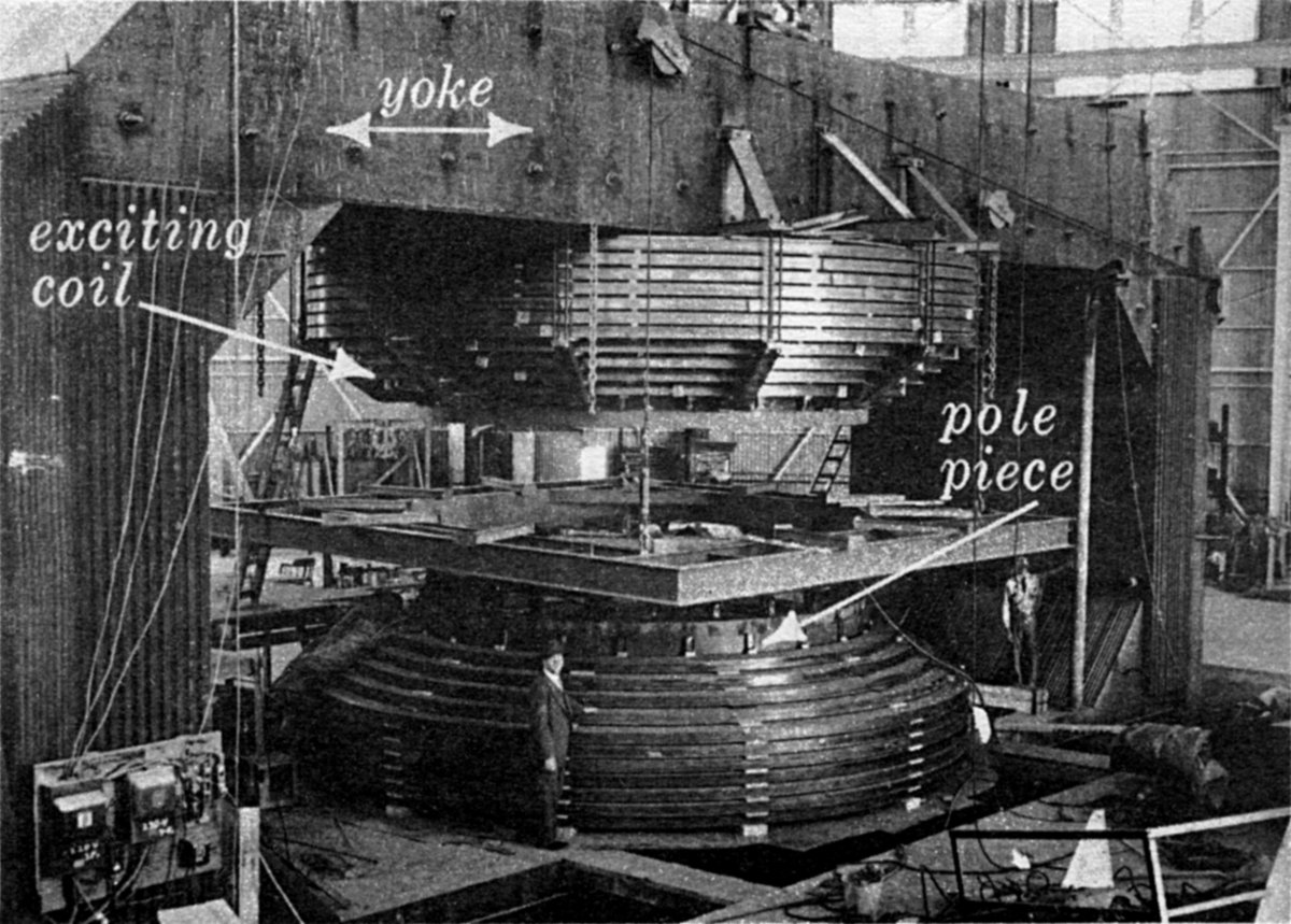 Fig. 1. The electromagnet under construction during the period 1940 to 1942.
Before the new cyclotron could be finished World War II began. Construction on the cyclotron was therefore halted. However, because of interest in separating the [Pg 3]isotopes of uranium by the electromagnetic method, work on the giant magnet continued at an even faster pace. This magnet would contain 3700 tons of steel in its yoke and pole pieces, and 300 tons of copper in its exciting coils (Fig. 1). By May 1942 the magnet was completed. During that summer it was used in a pilot plant to separate the first significant amounts of U235 ever obtained. The 184-inch magnet remained in use in a research and development program at Berkeley until the end of the war, supplying information to Oak Ridge, Tennessee, where a large separation plant had been erected.
Construction on the rest of the cyclotron was resumed in 1945. By that time a new principle had been discovered which made it possible to obtain ion beams of much higher energy than originally hoped for. Yet a considerably lower accelerating voltage could be used. This important discovery was made independently by Dr. V. Veksler in Russia and by Dr. Edwin M. McMillan, present Director of the Lawrence Radiation Laboratory. Before attempting to discuss this principle, we should first review the operation of a conventional cyclotron.
PRINCIPLE OF OPERATION OF A CONVENTIONAL CYCLOTRON
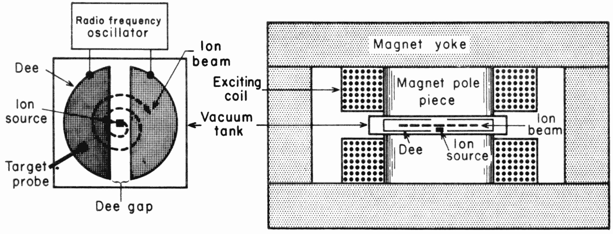 Fig. 2. Basic parts of a cyclotron.
The main parts of a cyclotron are represented in Fig. 2. Charged particles (ions) are accelerated inside an evacuated tank. This is to prevent the beam from colliding with [Pg 4]air molecules and being scattered. The vacuum tank is placed between the poles of an electromagnet, whose field bends the ion beam into a circular orbit.
The operation begins when the ions are introduced into the region between two accelerating electrodes, or "dees."[2] Because the ions carry a positive electric charge, they are attracted toward that dee which is electrically negative at the moment. Were it not for the magnetic field, the ions would be accelerated in a straight line; instead they are deflected into a circular path back toward the dee gap. By the time the ions again reach the dee gap, the sign of the electric potential on the dees is reversed, so that now the ions are attracted toward the opposite dee.
As this process of alternating the electric potential is repeated, the ions gain speed and energy with each revolution. This causes them to spiral outward. Finally they strike a target inserted into their path or are extracted from the cyclotron for use as an external beam.
The time required for an ion to complete one loop remains constant as it spirals outward. This is because its velocity increases sufficiently to make up for the increased distance it travels during each turn. This means that the electric potential applied to the dees must alternate at a constant frequency, called the "resonant frequency."
The resonant frequency f is given by the relationship
| f = | He
2 π m c |
(1) |
where H, e, π, c, and m are constants. H is the strength of the magnetic field of the cyclotron, e is the electric charge carried by the ion, π equals 3.14, c is a conversion factor, and m is the mass of the ion. For example, the [Pg 5]resonant frequency for protons accelerated in a 15,000-gauss magnetic field is 23.7 megacycles (Mc).[3] We call such a rapidly alternating potential a "radiofrequency voltage" and the electronic circuit for producing it a "radiofrequency oscillator."
The energy E of an ion emerging from the cyclotron is given by
| E = | H2 R2
2 |
e2
mc2 |
(2) |
where H, e, and m are as defined above, and R is the radius at which the beam is extracted. From this equation we see that for a given type of ion (where e and m are constant), the energy depends on the diameter and strength of the magnet, but not directly upon the voltage applied to the dees.
The number of revolutions that an ion can make in a conventional cyclotron is limited to about 70 to 100. This is due to a very curious effect: as an ion is accelerated, its mass increases! [This phenomenon is explained by Einstein's special theory of relativity (see Fig. 3).] Referring back to Eq. (1), we see that if the ion mass (m) does not remain constant, but rather increases, then the resonant frequency (f) decreases. But since the dee potential continues alternating at a constant frequency, an ion soon begins to arrive "late" at the dee gap. By the time it has made about 70 to 100 turns an ion is so badly out of phase that it is no longer accelerated.
Suppose now that we want to obtain an energy of 10 Mev. Because an ion can make a maximum of about 100 [Pg 6]turns, the accelerating potential would have to be about 100,000 volts. However, Professor Lawrence hoped to reach 100 Mev with the new 184-inch cyclotron. This meant that the accelerating voltage would have to be about 1,000,000 volts. Preventing such a high voltage from sparking promised to be one of many formidable engineering problems.
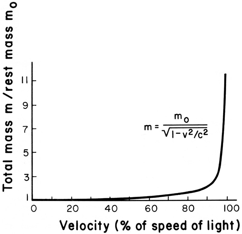 Fig. 3. Graph showing how the mass of an object increases as its velocity approaches that of light.
THE PRINCIPLE OF PHASE STABILITY
Fortunately, Drs. Veksler and McMillan showed that relatively low dee voltages can be used to accelerate ions to very high energies. This is possible if the oscillator [Pg 7]frequency is continuously decreased to keep it in synchronism with the decreasing rotational frequency of the ions. This would allow an ion to make many revolutions without becoming out of phase. This principle of phase stability was experimentally verified with the 37-inch cyclotron before being incorporated into the design of the 184-inch machine. Because it utilizes this principle, this machine has usually been referred to as a "synchrocyclotron" or "frequency-modulated cyclotron." However, it is sometimes called simply a "cyclotron."
The 184-inch synchrocyclotron was first operated in November 1946. With a maximum dee voltage of only 20,000 volts, it accelerated deuterons to 190 Mev and alpha particles to 380 Mev.[4] In 1949 it was modified to permit production of 350-Mev protons also.
Between 1955 and 1957 the synchrocyclotron was rebuilt so that now the following energies can be obtained:
| Protons | Deuterons | Alpha Particles | Helium-3 nuclei[5] |
| 730 Mev | 460 Mev | 910 Mev | 1140 Mev |
In reaching an energy of 730 Mev a proton, for example, makes 75,000 revolutions in just 6 milliseconds (msec). It travels a distance of 450 miles and attains a velocity of 152,000 miles per second, or 82% of the speed of light! During this brief journey its mass increases 75%, giving very convincing evidence for the validity of Einstein's theory. Similar data for other ions may be found in the appendix.
DESIGN AND CONSTRUCTION OF THE 184-INCH SYNCHROCYCLOTRON
Magnet
During the rebuilding of the cyclotron, the diameter of the magnet pole pieces was increased from 184 to 188-3/4 inches. Also, the pole gap at the center was reduced from 21 to 14 inches. These changes increased the weight of steel in the magnet from 3700 to 4000 tons.
The main exciting coils, which contain 1300 turns of copper-bar conductor each, were not altered. Two auxiliary coils containing 425 turns each were added. This brought the total weight of copper from 300 to 340 tons. The coils are layer-wound around the pole pieces close to the pole gap. Other data about the coils are given in the appendix.
The effect of these modifications was to increase the field strength at the center of the pole gap from 15,000 to 23,400 gauss. This increase made it possible to obtain the higher-energy ions.
Power is supplied to the coils by two motor generator sets, which produce the direct current required for a steady magnetic field. The direct current from the motor generators is regulated so that the magnetic-field fluctuation is less than one part in 10,000. This is necessary if one wants an external beam of nearly uniform energy.
In order to prevent the beam from becoming unstable and striking the dee, the magnetic field must be strongest at the center and decrease radially (Fig. 4a). With flat pole faces the field does not decrease uniformly. To give the desired rate of decrease, the pole faces are shimmed with concentric steel rings of varying thickness, as shown in Fig. 4b. In a radially decreasing magnetic field, the lines of magnetic flux bow outward, as represented in Fig. 4b. Ions moving in a magnetic field are deflected at right angles to these flux lines. Ions above the midplane of the cyclotron are directed downward; those below the midplane are directed upward. In this way an ion oscillates about the midplane and vertical focusing is achieved.
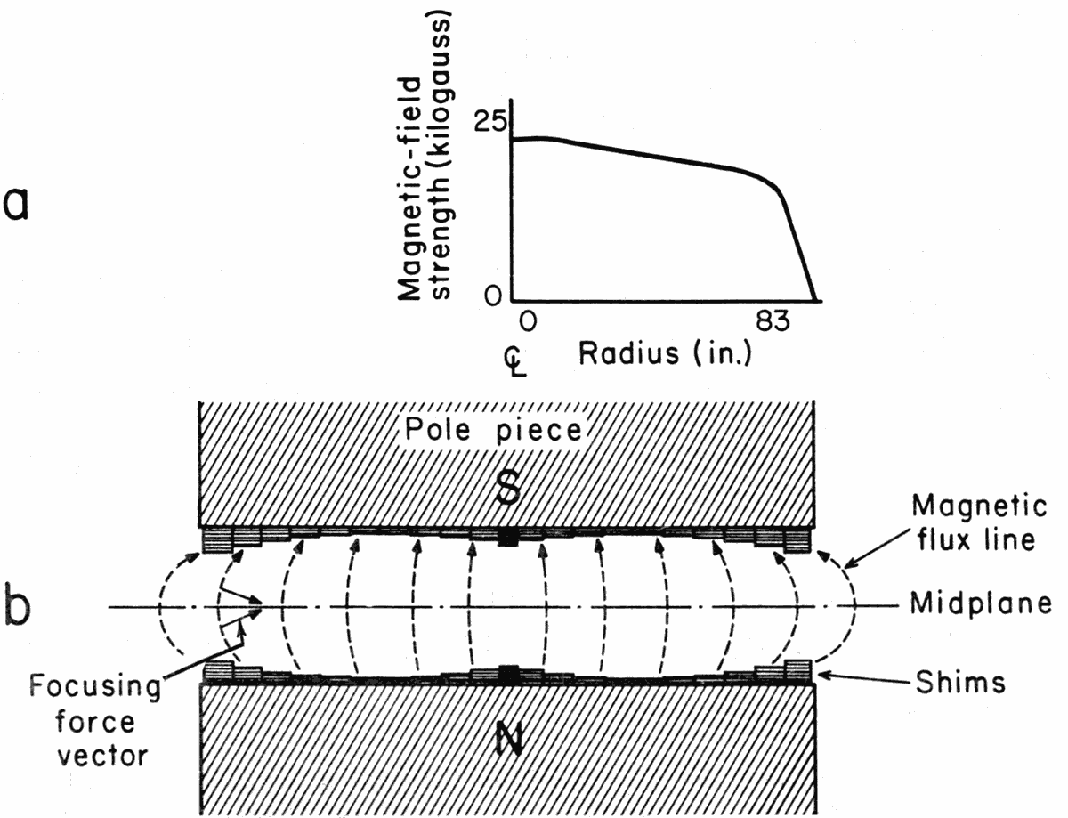 Fig. 4. (a) Plot of magnetic-field strength vs radius. The field strength decreases gradually out to a radius of about 83-in., after which it falls off sharply. This point marks the maximum usable radius for particle orbits. Further out they are unstable. (b) Magnetic flux lines are represented as broken arrows, and focusing forces as solid arrows. An ion above the midplane is directed downward, while an ion below the midplane is directed upward.
Radial focusing is accomplished in a somewhat analogous manner. If the magnetic field decreases with radius, radial restoring forces are established. An ion at too large a radius is directed inward, and an ion at too small a radius is directed outward. In this fashion, the ion oscillates about the synchronous orbit. Thus, radial focusing is achieved.
Vacuum System
The vacuum tank (acceleration chamber) is a steel box 20 × 25 ft and 4 ft high. It is evacuated to a pressure of 10-5 millimeter of mercury (about one 100-millionth of atmospheric pressure). The pumping equipment consists of [Pg 10]six oil-diffusion pumps and four mechanical vacuum pumps. The pumping speed of the six 20-in. oil-diffusion pumps is a total of 20,000 liters/sec.
Ion Source
The ion source is a simple arc-type. Hydrogen gas is allowed to leak into the ion-source enclosure near a tungsten filament, which is heated to incandescence. Electrons emitted by the filament knock off electrons from hydrogen atoms, leaving free protons. The protons then escape into the acceleration chamber through a hole in the ion-source housing. Once inside, the protons are accelerated by the dee potential.
Deuterons or alpha particles are obtained in a similar fashion using deuterium or helium gas in place of hydrogen.
Radiofrequency System
The 184-inch synchrocyclotron has a single dee instead of the double-dee arrangement described above for illustrative purposes. The accelerating electric field is developed between the dee and a dummy dee which is grounded to the vacuum tank. Using a single dee does not change the principle of operation, yet it offers the advantage of allowing more space for auxiliary equipment inside the vacuum tank. Also, the construction is much simpler. The dummy dee is not essential for operation, but it does improve performance.
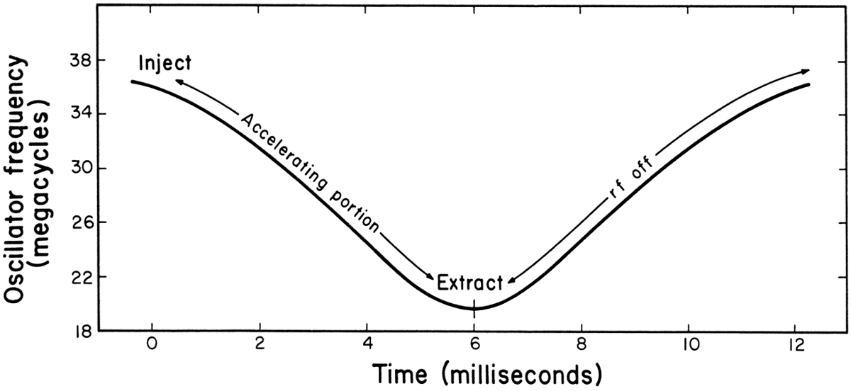 Fig. 5. Radiofrequency cycle for accelerating protons. Sixty-four such cycles are repeated each second.
Radiofrequency power is supplied to the dee by a vacuum-tube oscillator. The frequency of oscillation must decrease during the acceleration cycle, as indicated above. For protons, the frequency at the start of acceleration is 36 megacycles (Mc). At the end of acceleration the frequency is only 18 Mc (see Fig. 5). This change in frequency is achieved by varying the electrical capacitance in the tuned circuit of the oscillator. (This is what you do when you dial a different station on a radio.) This tuned circuit, which is called the cyclotron resonator, is shown in Fig. 6.
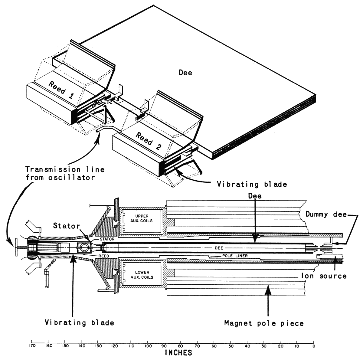 Fig. 6. Cyclotron resonator.
Because the frequency must change over such a wide range (from 36 to 18 Mc), the electrical capacitance must be varied by a factor of 20 to 1. This is done by a variable capacitor of unique design. It resembles two giant tuning forks. As the blades of the tuning forks vibrate, the capacitance is alternately increased and decreased by the required amount.
These two tuning forks must be kept in step with great precision. This is to prevent the oscillator from exciting lateral rf resonances. With a cyclotron of this size, this is a problem. These resonances, if excited, would cause loss of beam. The method for keeping the blades moving together is as follows: The blades are made to vibrate at their resonant frequency, which is approximately 64 cycles per second. One set of blades operates at its natural frequency as a tuning-fork oscillator. The second set of blades is driven from an amplified sample of the signal from the first; its natural period is adjusted automatically to equal that of the first. The amplitude of each set is regulated to within 0.003 in.; the phase angle between the blades is regulated to within 1 deg.
Ions are accelerated only when the radiofrequency is decreasing (Fig. 5). The remaining portion of the cycle is "dead time." Thus, 64 pulses, each of about 500 microseconds' duration, are obtained every second. The average ion current of a pulsed beam is much less than for a continuous beam, such as that obtained from a conventional cyclotron (see Table I). This is part of the price paid for higher energies.
Internal Targets and Beam Extractor
The simplest target is one placed inside the vacuum tank where the circulating beam will strike it. The target may be any substance that the physicist or chemist wants to irradiate. The target material is attached to a movable probe. If the experimenter wants to use the full-energy beam, he places the target at the maximum usable radius [Pg 13]of the circulating beam (82 inches). However, if he desires to use ions having less than the maximum energy, he inserts the target further into the cyclotron so that it is intercepted sooner.
TABLE I
| Comparison of external-beam energy and current for a synchrocyclotron and a conventional cyclotron |
|||
| 184-Inch Synchrocyclotron | |||
| Protons | Deuterons | Alpha particles | |
| Beam energy — maximum (Mev) | 730 | 460 | 910 |
| Beam intensity — peak current (μa)[a] | 120 | 120 | 40 |
| Beam intensity — average current (μa) | 0.75 | 0.75 | 0.25 |
| 60-Inch Cyclotron | |||
| Beam energy — maximum (Mev) | 12 | 24 | 48 |
| Beam intensity — peak current (μa) | 100 | 150 | 100 |
| Beam intensity — average current (μa) | 70 | 80 | 60 |
| [a] μa = microampere | |||
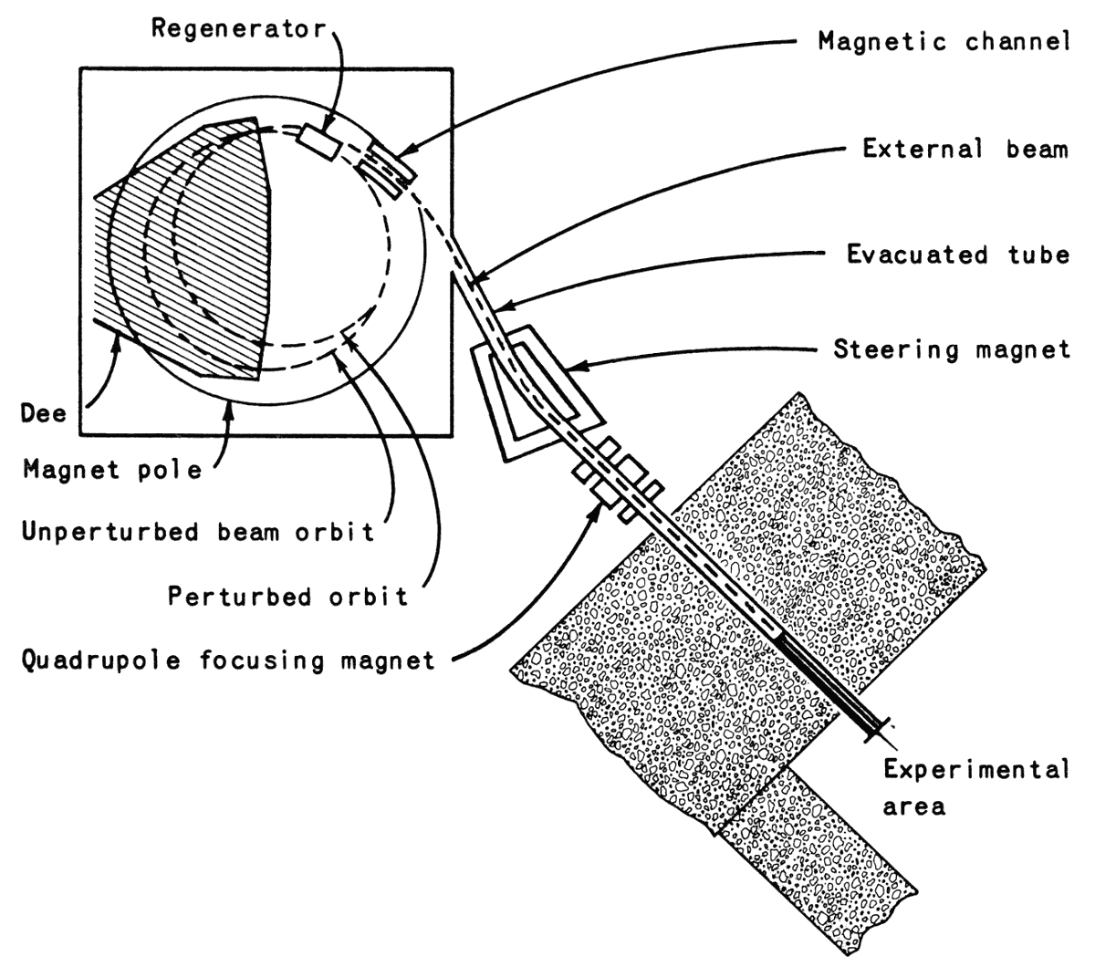 Fig. 7. Plan view of the cyclotron, showing the method for obtaining an external beam of protons, deuterons, or alpha particles.
Some experiments require an external beam of protons, deuterons, or alpha particles. A beam of this type can be brought out of the machine by means of a LeCouteur regenerator (Fig. 7). The construction of the regenerator is very simple. It is made of a number of steel laminations of various sizes. What the regenerator does is perturb the magnetic field of the cyclotron at one radial position. Each time the beam passes through the regenerator it receives a kick. With each kick the beam builds up its radial amplitude, until finally it enters a magnetic channel. This channel focuses the beam and steers it outside the main magnetic field. Once outside, the beam travels through an evacuated tube, which is integral with the main vacuum tank. By means of a steering magnet, the beam can be sent into [Pg 15]either the physics cave or the medical cave. (These experimental areas are called "caves" because they are rooms inside the massive concrete shielding wall.)
Other experiments may require an external beam of mesons.[6] A meson beam is obtained in the following way (Fig. 8): A movable target such as a block of carbon is placed inside the cyclotron near the end of the outward-spiraling proton beam. When the proton beam hits this target, a shower of mesons is produced. These mesons are bent in various directions by the main magnetic field. Some of them pass through a thin metal window in the vacuum-tank wall and are focused by a magnetic lens into a beam. This meson beam then travels through a hole in the concrete shielding wall into the meson cave. The maximum intensity of this extracted meson beam depends on both the charge and energy desired. Beams of more than 100,000 mesons per second have been obtained through an aperture 4 × 4 in. in the shielding wall.
CYCLOTRON EXPERIMENTS
Nuclear Physics
About 86% of the operating time of the 184-inch synchrocyclotron is devoted to experiments in nuclear physics. Most of the experiments study the production and interaction of π mesons. These particles are considered to be essential factors in the intense but short-range forces that bind the nucleus together. The three types of π mesons are designated according to their electric charge as π+, π0, and π-.[7] These mesons materialize only in high-energy nuclear collisions.
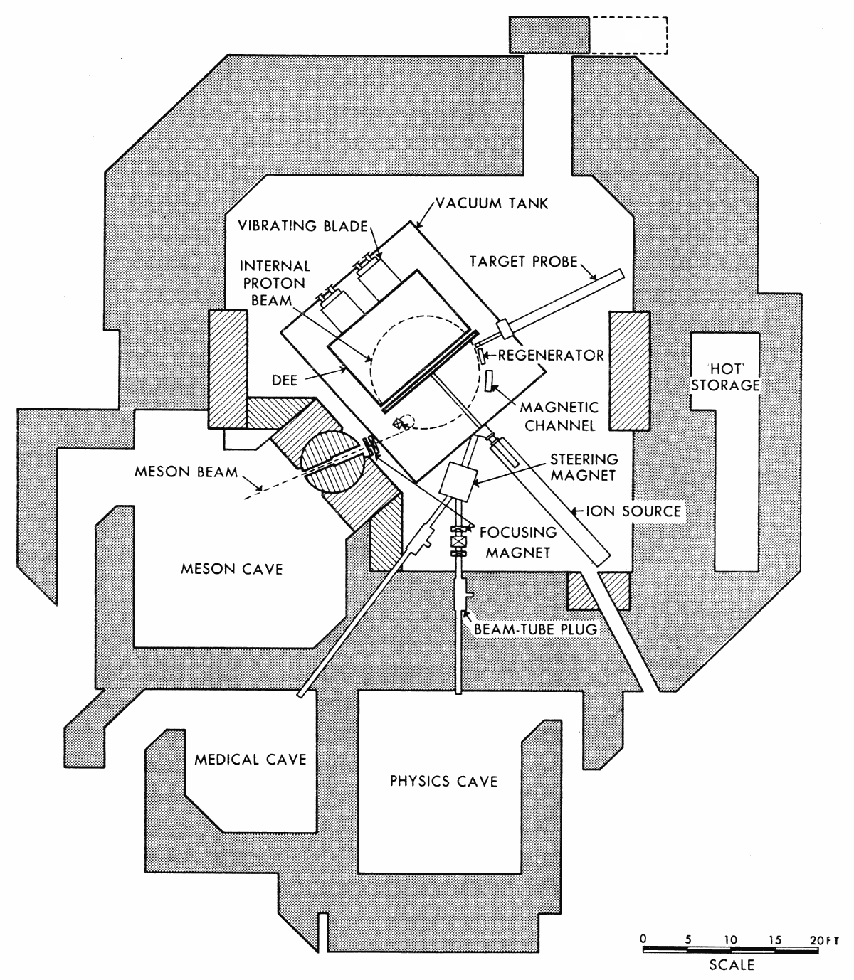 Fig. 8. Method for obtaining external meson beam.
Of great importance are those experiments that determine the probability of producing each of the three types of mesons in a nuclear collision. This type of experiment is repeated for different beam energies and target elements. Other experiments measure the energy and direction of emission of π mesons from a target.
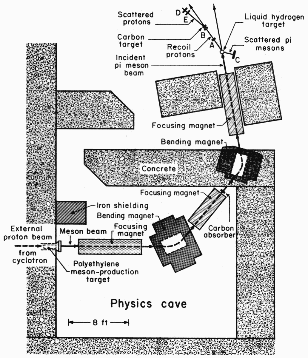 Fig. 9. A typical experiment. Scintillation counters at A, B, C, D, and E record the passage of charged particles.
A typical π-meson experiment is represented in Fig. 9. The purpose of this experiment was to detect the spin directions of protons as they are knocked out of a liquid hydrogen target by a π-meson beam. (Like the earth, a proton spins on its axis.) An extracted proton beam from the cyclotron enters the physics cave from the left, striking a polyethylene target and producing π mesons. A beam of these mesons is formed by a series of two bending magnets and three focusing magnets. This beam passes through a carbon absorber to remove unwanted particles. The meson beam then strikes the liquid hydrogen target. A few of the incoming mesons scatter, knocking protons out of the liquid hydrogen. Scintillation counters at A and B record the passage of a proton, thus defining its direction. The scattered mesons are counted by a scintillation counter at C. A few of the protons scatter off the carbon target and are detected by counters at E and D. From the detection of such events, the spin directions (polarization) of the recoil protons can be analyzed. In this way, more is learned about the fundamental π-proton interaction.
Further studies of the interactions of π mesons are made in the meson cave. Other experiments performed there are concerned with μ mesons. The μ meson (muon) is a particle created in the decay of a π meson and is the principal constituent of cosmic rays striking the surface of the earth. The muon is unstable, eventually undergoing a radioactive decay into an electron. Although the muon does not experience nuclear forces, it can interact weakly with nuclei. The behavior of the muon is well understood, but its role as one of the elementary particles is unknown. That is, if the muon did not exist, what effect would this have on the structure of matter? The answer to this question, among others, is being sought by physicists using the 184-inch cyclotron.
Biophysics
Experiments in biophysics are conducted in the medical [Pg 19]cave. In these the interest lies not in nuclear interactions but in the effect of ionizing radiation on living tissue. High-energy beams of particles can be used for selective destruction of specific areas of the brain. This permits physiological mapping of the functions of the brain in experimental animals. It further offers a therapeutic approach to the treatment of brain tumors. One of the important investigational programs is concerned with the relationship of the pituitary gland to the growth rate of certain cancers and to some endocrine disorders.
Nuclear Chemistry
For techniques of radiochemistry to be employed successfully, high interaction rates (and therefore high beam intensities) are needed. For this reason, chemistry targets are usually inserted right into the cyclotron so that they can be bombarded directly by the circulating beam. After the bombardment is completed the target is removed from the cyclotron. It is then taken to a chemistry laboratory and subjected to detailed chemical procedures. Individual elements are removed, and the radioactive isotopes of each element are identified by quantitative counting techniques. In some cases a mass spectrometer is used to analyze the products. Many deductions about the nature of the breakup of the target nucleus can be drawn from the pattern of the observed radioactive products. Sometimes the nucleus splits almost in half. This is called fission. More frequently smaller parts of the nucleus are split off. Two general types of reactions, known as spallation and fragmentation, are distinguished. One of the goals of this research is to learn more about the constitution of the nucleus and of the forces which bind the particles in the interior of the nucleus.
FOOTNOTES:
[1] The grants were as follows: Rockefeller Foundation—$1,150,000; John and Mary Markle Foundation—$25,000; The Research Corporation—$50,000. The University of California added a guarantee of $175,000 to bring the total building fund to $1,400,000.
[2] In the first cyclotrons the electrodes were shaped like the letter "D."
[3] We have the values H = 15,000 gauss, e = 4.8 × 10⁻¹⁰ electrostatic units, and m = 1.6 × 10⁻²⁴ gram. To find f, we write
| f |
|
|||||
| f | = 23.7 Mc. |
[4] A deuteron is the nucleus of an atom of heavy hydrogen and contains one proton and one neutron; it carries a single positive electric charge. An alpha particle is the nucleus of a helium atom and is made up of two protons and two neutrons; it carries two positive charges.
[5] The machine is equipped for helium-3 operation, but to date it has not been used for that purpose.
[6] Mesons are elementary particles intermediate in mass between the electron and proton.
[7] It may be interesting to note that the π0 meson was discovered with this cyclotron in 1950. This was the first particle to be discovered with an accelerator. All particles that had been previously discovered were observed first in cosmic rays or some other form of natural radiation.
BIBLIOGRAPHY
- Gerald A. Behman, Particle Accelerators: I. Bibliography, II. List of Accelerator Installations, UCRL-8050, January 1, 1958.
- Samuel Glasstone, The Acceleration of Charged Particles, in Sourcebook on Atomic Energy, Second Edition (Van Nostrand, Princeton, 1958), Ch. IX.
- M. S. Livingston, High-Energy Accelerators (Interscience Publishers, New York, 1954).
- M. Stanley Livingston and Edwin M. McMillan, History of the Cyclotron, Physics Today 12, 18-34 (October 1959).
- E. M. McMillan, Particle Accelerators, in Experimental Nuclear Physics, Emilio Segrè, Editor, Vol. III (Wiley, New York, 1959), Part XIII.
- Bob H. Smith et al., The Electrical Aspects of the UCRL 740-Mev Synchrocyclotron, UCRL-3779 Rev., October 2, 1957.
- Robert L. Thornton, Frequency-Modulation and Radiofrequency System for the Modified Berkeley Cyclotron, UCRL-3362, April 3, 1956.
- Robert R. Wilson, Particle Accelerators, Scientific American 198, 64-76 (March 1958).
APPENDIX
SUMMARY OF SPECIFICATIONS
| Present fields of research | % of time |
| Nuclear physics | 86 |
| Nuclear chemistry | 2 |
| Biophysics | 12 |
| Scheduled operation | 156 hours/week |
Performance
Internal Beams
| Protons | Deuterons | Alpha particles | Helium-3 ions | |
| Maximum energy (Mev) | 730 | 460 | 910 | 1140 |
| Energy spread (Mev) | 55 | |||
| Beam intensity | ||||
| Average current (μa) | 0.75 | 0.75 | 0.25 | |
| Peak current (μa) | 120 | 120 | 40 | |
| Beam radius, maximum (in.) | 82 | 82 | 82 | 82 |
| Time required for acceleration (msec) | 6 | 4.5 | 4.5 | |
| Number of revolutions during acceleration | 75,000 | 60,000 | 60,000 | |
| Distance traveled during acceleration (miles) | 450 | 360 | 360 | |
| Velocity at maximum energy (% of speed of light) | 82 | 60 | 60 | 69 |
| Mass increase at maximum energy (% of rest mass) | 75 | 25 | 25 | 40 |
| Range of full-energy particles (in. of aluminum) | 37 | 12 | 7 |
External Beams
| Physics cave | Meson cave | ||||||
| Protons | Neutrons | π+ | π+ | π- | |||
| Energy (Mev) | 730 | 310 | 100 | 250 | 100 | 300 | |
| Energy spread (Mev) | 14 | 10 | 20 | 10 | 30 | ||
| Beam area (cm2) | 25 | 40 | 100 | 100 | 100 | 100 | |
| Flux (particles/cm2-sec) | 2×10¹⁰ | 5×10⁵ | 5×10⁴ | 1000 | 100 | 1500 | 1000 |
Acceleration chamber (vacuum tank)
| Size | |
| length (ft) | 25 |
| width (ft) | 20 |
| height (ft) | 4 |
| Material: mild steel | |
| Operating pressure (mm Hg) | 10-5 |
| Vacuum pumps: six 20-in. oil-diffusion pumps with 8-in. boosters: one Beach-Russ 750-cfm; one Kinney 300-cfm; two Kinney 105-cfm. |
|
| Pumping speed of oil-diffusion pumps (liters/sec) | 20,000 |
Magnet
| Core diameter (in.) | 184 |
| Pole-tip diameter (in.) | 188.75 |
| Pole gap at center (in.) | 14 |
| Magnetic field strength (gauss) | |
| at center | 23,400 |
| at radius of 82.2 in., where n = 0.2 | 22,275 |
| Weight of steel (tons) | 4,000 |
| Magnet coils | Main coils | Auxiliary coils |
| material | solid copper (1/4 × 4 in.) |
hollow copper (1-3/16 × 1-1/16 in.) |
| weight of copper (tons) | 300 | 40 |
| number of turns (total) | 2,600 | 425 |
| ampere turns | 1.9 × 10⁶ | 1.1 × 10⁶ |
| current (amp) | 1600 | 2800 |
| voltage (v) | 550 | 560 |
| power (kw) | 900 | 1600 |
| coolant | oil | water |
Radiofrequency system
Dee system
| number of dees | 1 |
| size | |
| length (in.) | 126 |
| width (in.) | 180 |
| height (in.) | 48 |
| material: 1/64-in.-thick copper, stretched over a stainless steel frame | |
| dee aperture (in.) | 4-3/16 |
Oscillator
| type: self-excited grounded-grid | 10 |
| tube: one Machlett ML5681 | |
| dc input, operating condition (kw) | 10 |
| dee bias, maximum dc (v) | 2000 |
| Protons | Deuterons | Alpha particles | |
| rf duty cycle (%) | 38 | 28 | 28 |
| dee-to-ground voltage, peak (kv) | 9 | 6 | 6 |
Frequency-modulation system
| type: vibrating-reed (tuning-fork) capacitor | number of units: two (two blades each) |
| blades | |
| size | |
| width (in.) | 45 |
| length (in.) | 32 |
| thickness: tapered from 1.4 to 0.06 in. | |
| weight (lb) | 500 |
| vibrational frequency (cps) | 64 |
| electrical capacitance (μμf) | 300 to 6,500 |
| peak-to-peak excursion (in.) | 1 |
| minimum separation of blade and stator (mils) | 50 |
| Protons | Deuterons | Alpha particles | |
| frequency sweep (Mc) | 36-18 | 18-13.5 | 18-13.5 |
Ion source: conventional open-arc type
Beam extractor
LeCouteur-type regenerator combined with magnetic channel
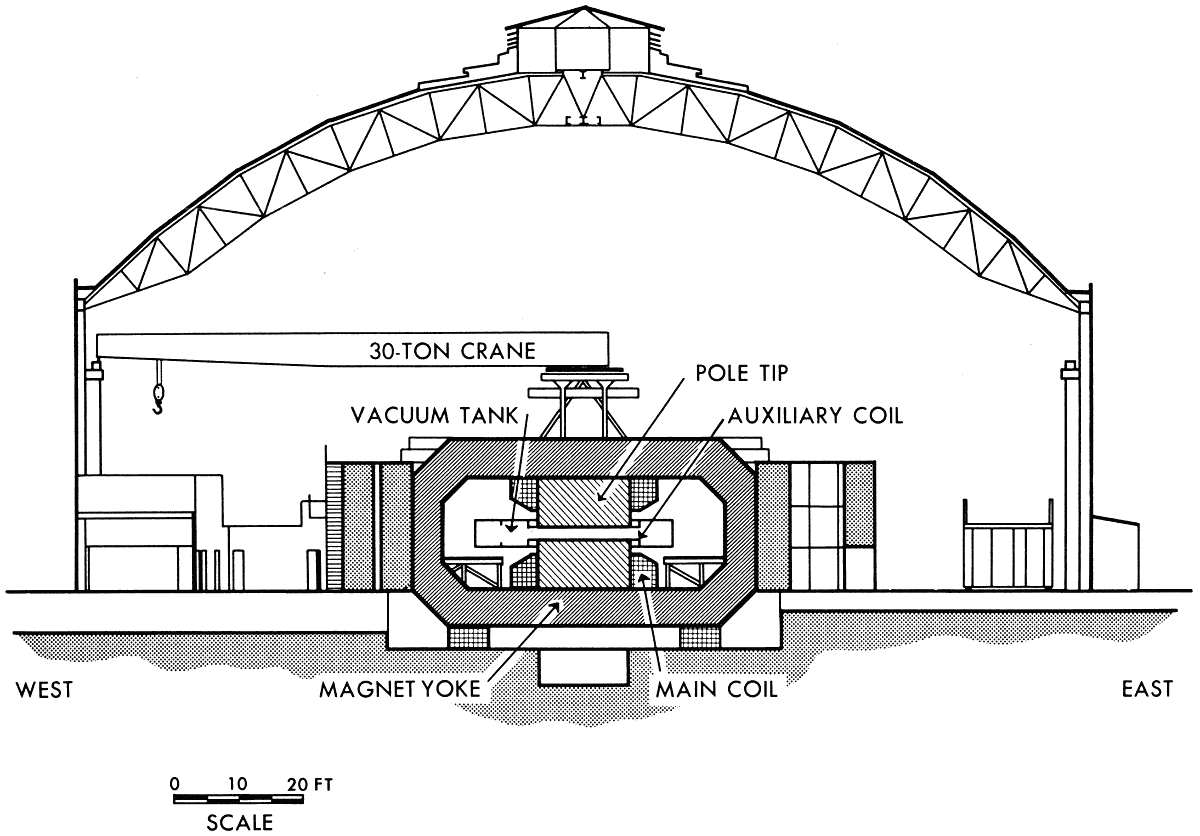
Building and facilities
| Room dimensions | |
| diameter (ft) | 160 |
| height (ft) | 90 |
| Crane | |
| type: radial | |
| capacity (tons) | 30 |
| overhead span (ft) | 77 |
| Concrete shielding: 15 ft thick on sides, 4 ft on top | |
History
| Design started: January 1940. |
| Construction started: August 1940. |
| First operation |
| for deuterons and alpha particles: November 1946. |
| for protons: December 1948. |
| Rebuilt: 1955-1957. |
 Synchrocyclotron Building
Pub. No. 2d
5M
June 1964